29.06.2020
A simple voltage stabilizer for a flashlight. Low voltage voltage converters for LEDs. Making a modern flashlight
Let's consider LED products, ranging from old 5 mm to super-bright high-power LEDs whose power reaches 10 W.
To choose the “right” flashlight for your needs, you need to understand what kinds of LED flashlights there are and their characteristics.
What diodes are used in flashlights?
High-power LED lights started with 5mm sensor devices.
LED flashlights in completely different designs, from pocket to camping, became widespread in the mid-2000s. Their price has dropped noticeably, and the brightness and long service life of a single battery charge have played their role.
 5mm white ultra-bright LEDs consume 20 to 50 mA of current, with a voltage drop of 3.2-3.4 volts. Luminous intensity – 800 mcd.
They perform very well in miniature keychain flashlights. Small size allows you to carry this flashlight with you. They are powered either by “mini-pen” batteries or by several round “tablets”. Often used in flashlight lighters.
These are the types of LEDs that have been installed in Chinese lanterns for many years, but their life is gradually coming to an end.
In search lights when large size reflectors, it is possible to mount dozens of such diodes, but such solutions are gradually fading into the background, and the choice of buyers falls in favor of flashlights with powerful Cree-type LEDs.
 Search light with 5mm LEDs
 These flashlights operate on AA, AAA batteries or rechargeable batteries. They are inexpensive and inferior both in brightness and quality to modern flashlights with more powerful crystals, but more on that below.
In the further development of flashlights, manufacturers went through many options, but the market quality products occupied by flashlights with powerful matrices or discrete LEDs.
What kind of LEDs are used in high-power flashlights?
Powerful flashlights mean modern flashlights various types ranging from those the size of a finger to huge search lights.

In such products, the Cree brand is relevant in 2017. This is the name of an American company. Its products are considered one of the most advanced in the field of LED technology. An alternative is LED from the manufacturer Luminus.
Such things are significantly superior to LEDs from Chinese lanterns.
What Cree LEDs are most commonly installed in flashlights?
Models are called consisting of three or four characters, separated by a hyphen. So diodes Cree XR-E, XR-G, XM-L, XP-E. Models XP-E2, G2 are most often used for small flashlights, while XM-L and L2 are very versatile.
They are used starting from the so-called. EDC flashlights (everyday carry) range from small flashlights smaller than the palm of your hand to large, serious search flashlights.
Let's look at the characteristics of high-power LEDs for flashlights.
| Name | Cree XM-L T6 | Cree XM-L2 | Cree XP-G2 | Cree XR-E |
| Photo |  |
|||
| U, V | 2,9 | 2,85 | 2,8 | 3,3 |
| I, mA | 700 | 700 | 350 | 350 |
| P, W | 2 | 2 | 1 | 1 |
| Operating temperature, °C | ||||
| Luminous flux, Lm | 280 | 320 | 145 | 100 |
| Illumination angle, ° | 125 | 125 | 115 | 90 |
| Color rendering index, Ra | 80-90 | 70-90 | 80-90 | 70-90 |
The main characteristic of LEDs for flashlights is luminous flux. The brightness of your flashlight and the amount of light that the source can provide depends on it. Different LEDs, consuming the same amount of energy, can differ significantly in brightness.
Let's look at the characteristics of LEDs in large floodlight flashlights :
| Name | ||||
| Photo |  |  |  |  |
| U, V | 5,7; 8,55; 34,2; | 6; 12; | 3,6 | 3,5 |
| I, mA | 1100; 735; 185; | 2500; 1250 | 5000 | 9000...13500 |
| P, W | 6,3 | 8,5 | 18 | 20...40 |
| Operating temperature, °C | ||||
| Luminous flux, Lm | 440 | 510 | 1250 | 2000...2500 |
| Illumination angle, ° | 115 | 120 | 100 | 90 |
| Color rendering index, Ra | 70-90 | 80-90 | 80-90 |
Sellers often do not indicate the full name of the diode, its type and characteristics, but an abbreviated, slightly different alphanumeric marking:
- For XM-L: T5; T6; U2;
- XP-G: R4; R5; S2;
- XP-E: Q5; R2; R;
- for XR-E: P4; Q3; Q5; R.
The flashlight may be called “EDC T6 Flashlight”, there is more than enough information in such brevity.
Flashlight repair
Unfortunately, the price of such flashlights is quite high, as are the diodes themselves. And it is not always possible to purchase a new flashlight in case of a breakdown. Let's figure out how to change the LED in a flashlight.
To repair a flashlight, you need a minimum set of tools:
- Soldering iron;
- flux;
- solder;
- screwdriver;
- multimeter
To get to the light source you need to unscrew the head of the flashlight; it is usually attached to a threaded connection.

In diode test or resistance measurement mode, check the serviceability of the LED. To do this, touch the black and red probes to the LED terminals, first in one position, and then swap the red and black ones.

If the diode is working properly, then in one of the positions there will be low resistance, and in the other - high. This way you determine that the diode is working and conducts current in only one direction. The diode may emit faint light during testing.
Otherwise, there will be a short circuit or high resistance (open) in both positions. Then you need to replace the diode in the flashlight.

Now you need to unsolder the LED from the flashlight and, observing the polarity, solder in a new one. Be careful when choosing an LED, consider its current consumption and the voltage for which it is designed.
If you neglect these parameters, in the best case the flashlight will quickly dry up, in the worst case the driver will fail.
A driver is a device for powering an LED with a stabilized current from different sources. Drivers are manufactured industrially for power supply from a 220 volt network, from a car electrical network - 12-14.7 volts, from Li-ion batteries, for example, size 18650. Most powerful flashlights are equipped with a driver.
Increasing the power of the flashlight
If you are not satisfied with the brightness of your flashlight or you have figured out how to replace the LED in a flashlight and want to upgrade it, before buying heavy-duty models, study the basic principles of LED operation and the limitations in their operation.
 Diode matrices do not like overheating - this is the main postulate! And replacing the LED in a flashlight with a more powerful one can lead to this situation. Pay attention to models in which more powerful diodes are installed and compare them with yours; if they are similar in size and design, change them.
If your flashlight is smaller, additional cooling will be required. We wrote more about making radiators with our own hands.
If you try to install such a giant as the Cree MK-R into a miniature keychain flashlight, it will quickly fail from overheating and it will be a waste of money. A slight increase in power (a couple of watts) is acceptable without upgrading the flashlight itself.
Otherwise, the process of replacing the brand of LED in a flashlight with a more powerful one is described above.
Police lights
 LED Police flashlight with shocker
 Such lanterns shine brightly and can act as a means of self-defense. However, they also have problems with LEDs.
How to replace the LED in a Police flashlight
The wide range of models is very difficult to cover in one article, but general recommendations for repairs can be given.
- When repairing a flashlight with a stun gun, be careful, preferably use rubber gloves to avoid electric shock.
- Flashlights with dust and moisture protection are assembled on large quantities screws They differ in length, so make notes from where you unscrewed this or that screw.
- The optical system of the Police flashlight allows you to adjust the diameter of the light spot. When disassembling the body, make marks on the position in which the parts were before removal, otherwise it will be difficult to put the unit with the lens back.
Replacing the LED, voltage converter unit, driver, and battery is possible using a standard soldering kit.
What kind of LEDs are used in Chinese lanterns?
Many products are now purchased on Aliexpress, where you can find both original products and Chinese copies that do not correspond to the stated description. The price for such devices is comparable to the price of the original.

In a flashlight that claims a Cree LED, it may not actually be there; at best, there will be a diode of a frankly different type, at worst, one that will be difficult to distinguish from the original in appearance.
 What might this entail? Cheap LEDs are made in low-tech conditions and do not produce the declared power. They have low efficiency, which is why they have increased heating of the case and crystal. As has already been said, overheating is the most evil enemy for LED devices.
This happens because when heated, the current through the semiconductor increases, as a result of which the heating becomes even stronger, the power is released even more, and this avalanche-like leads to breakdown or breakage of the LED.
If you try and spend time searching for information, you can determine the originality of the product.
 Compare the original and fake cree
 LatticeBright is a Chinese LED manufacturer that makes products very similar to Cree, probably a coincidence of design thought (sarcasm).
 Comparison of the Chinese copy and the original Cree
 On the substrates these clones look like this. You can notice the variety of shapes of LED substrates produced in China.
 Detecting counterfeit by LED substrate
 Counterfeits are made quite skillfully; many sellers do not indicate this “brand” in the product description and where the LEDs for flashlights are made. The quality of such diodes is not the worst among Chinese junk, but it is also far from the original.
Installing an LED instead of an incandescent lamp
Many people have horse races or incandescent lamps collecting dust in old things, and you can easily turn it into LED. For this, there are either ready-made solutions or homemade ones.
Using a broken light bulb and LEDs, with a little ingenuity and solder, you can make a great replacement.
In this case, an iron barrel is needed to improve heat removal from the LED. Next you need to solder all the parts to each other and secure with glue.
When assembling, be careful - avoid shorting the leads; hot glue or heat shrink tubing will help with this. The central contact of the lamp must be unsoldered - a hole will form. Pass the resistor lead through it.
Next you need to solder the free lead of the LED to the base, and the resistor to the central contact. For a voltage of 12 volts, a 500 Ohm resistor is needed, and for a voltage of 5 V – 50-100 Ohms, for power supply from a Li-ion 3.7V battery – 10-25 Ohms.
 How to make an LED lamp from an incandescent lamp
 Selecting an LED for a flashlight is much more difficult than replacing it. It is necessary to take into account a lot of parameters: from brightness and dispersion angle to heating of the case.
In addition, we must not forget about the power supply for the diodes. If you master everything described above, your devices will shine for a long time and with high quality!
Almost all motorists are familiar with the problem of rapid failure of LED lamps. Which are often placed in side lights, daytime running lights(DRL) or other lights.
Typically these LED bulbs have low power and current consumption. What, in fact, determines their choice.
The LED itself can easily serve in optimal conditions for more than 50,000 hours, but in a car, especially a domestic one, it is sometimes not enough for a month. First, the LED begins to flicker, and then completely burns out.
What explains this?
The lamp manufacturer writes the marking “12V”. This is the optimal voltage at which the LEDs in the lamp operate almost at maximum. And if you supply 12 V to this lamp, it will last at maximum brightness for a very long time.So why does it burn out in the car? Initially, the voltage of the car’s on-board network is 12.6 V. An overestimation of 12 is already visible. And the voltage of the network of a running car can reach up to 14.5 V. Let’s add to all this various surges from switching powerful high- or low-beam lamps, powerful voltage pulses and magnetic interference when starting the engine from the starter. And we get not the best network for powering LEDs, which, unlike incandescent lamps, are very sensitive to all changes.
Since often in simple Chinese lamps there are no limiting elements other than a resistor, the lamp fails due to overvoltage.
During my practice, I changed dozens of such lamps. Most of them did not serve even a year. Eventually I got tired and decided to look for an easier way out.
Simple voltage stabilizer for LEDs
To ensure comfortable operation for LEDs, I decided to make a simple stabilizer. Absolutely not difficult, any motorist can repeat it.All we need:
- - a piece of PCB for the board,
Stabilizer circuit

The circuit is taken from the datasheet for the L7805 chip.

It's simple - on the left is the entrance, on the right is the exit. Such a stabilizer can withstand up to 1.5 A load, provided that it is installed on a radiator. Naturally, for small light bulbs no radiator is needed.
Stabilizer assembly for LEDs
All you need to do is cut out the required piece from the PCB. There is no need to etch the tracks - I cut out simple lines with a regular screwdriver.Solder all the elements and you're done. No setup required.


Thermal blower serves as the housing.
Another advantage of the circuit is that it is fashionable to use a car body as a radiator, since the central terminal of the microcircuit body is connected to the minus.

That's all, the LEDs no longer burn out. I’ve been driving for more than a year and forgot about this problem, which I advise you to do as well.
The main electrical parameter of light emitting diodes (LEDs) is their operating current. When we see the operating voltage in the LED characteristics table, we need to understand that we're talking about about the voltage drop across the LED when operating current flows. That is, the operating current determines the operating voltage of the LED. Therefore, only a current stabilizer for LEDs can ensure their reliable operation.
Purpose and principle of operation
Stabilizers must provide a constant operating current for the LEDs when the power supply has problems with voltage deviations from the norm (you will be interested to know). A stable operating current is primarily necessary to protect the LED from overheating. After all, if the maximum permissible current is exceeded, the LEDs fail. Also, the stability of the operating current ensures the constancy of the luminous flux of the device, for example, when batteries are discharged or voltage fluctuations in the supply network.
Current stabilizers for LEDs have different types execution, and the abundance of design options is pleasing to the eye. The figure shows the three most popular semiconductor stabilizer circuits.
- Scheme a) - Parametric stabilizer. In this circuit, the zener diode sets a constant voltage at the base of the transistor, which is connected according to the emitter follower circuit. Due to the stability of the voltage at the base of the transistor, the voltage across the resistor R is also constant. By virtue of Ohm's law, the current across the resistor also does not change. Since the resistor current is equal to the emitter current, the emitter and collector currents of the transistor are stable. By including the load in the collector circuit, we obtain a stabilized current.
- Scheme b). In the circuit, the voltage across resistor R is stabilized as follows. As the voltage drop across R increases, the first transistor opens more. This leads to a decrease in the base current of the second transistor. The second transistor closes slightly and the voltage on R stabilizes.
- Scheme c). In the third circuit, the stabilization current is determined by the initial current of the field-effect transistor. It is independent of the voltage applied between drain and source.
In circuits a) and b), the stabilization current is determined by the value of the resistor R. By using a subline resistor instead of a constant resistor, you can regulate the output current of the stabilizers.
Electronic component manufacturers produce many LED regulator chips. Therefore, at present, integrated stabilizers are more often used in industrial products and amateur radio designs. Read about everything possible ways Connecting LEDs is possible.
Review of famous models
Most microcircuits for powering LEDs are made in the form of pulse voltage converters. Converters in which the role of a storage device is electrical energy performed by an inductor (choke) are called boosters. In boosters, voltage conversion occurs due to the phenomenon of self-induction. One of the typical booster circuits is shown in the figure.

The current stabilizer circuit works as follows. A transistor switch located inside the microcircuit periodically closes the inductor to the common wire. At the moment the switch opens, a self-induction EMF arises in the inductor, which is rectified by a diode. It is characteristic that the self-induction EMF can significantly exceed the voltage of the power source.
As you can see from the diagram, very few components are required to make a booster on the TPS61160 manufactured by Texas Instruments. The main attachments are inductor L1, Schottky diode D1, which rectifies the pulse voltage at the output of the converter, and R set.
The resistor performs two functions. Firstly, the resistor limits the current flowing through the LEDs, and secondly, the resistor serves as an element feedback(a kind of sensor). The measuring voltage is removed from it, and the internal circuits of the chip stabilize the current flowing through the LED at a given level. By changing the resistor value you can change the current of the LEDs.
The TPS61160 converter operates at a frequency of 1.2 MHz, the maximum output current can be 1.2 A. Using the microcircuit, you can power up to ten LEDs connected in series. The brightness of the LEDs can be changed by applying a variable duty cycle PWM signal to the “brightness control” input. The efficiency of the above circuit is about 80%.
It should be noted that boosters are usually used when the voltage across the LEDs is higher than the voltage of the power supply. In cases where it is necessary to reduce the voltage, linear stabilizers are often used. A whole line of such MAX16xxx stabilizers is offered by MAXIM. A typical connection diagram and internal structure of such microcircuits is shown in the figure.

As can be seen from block diagram, stabilization of the LED current is carried out by a P-channel field-effect transistor. The error voltage is removed from the resistor R sens and supplied to the field control circuit. Since the field-effect transistor operates in linear mode, the efficiency of such circuits is noticeably lower than that of pulse converter circuits.
The MAX16xxx line of ICs are often used in automotive applications. The maximum input voltage of the chips is 40 V, output current is 350 mA. They, like switching stabilizers, allow PWM dimming.
Stabilizer on LM317
As a current stabilizer for LEDs, you can use not only specialized chips. The LM317 circuit is very popular among radio amateurs.
LM317 is a classic linear voltage regulator with many analogs. In our country, this microcircuit is known as KR142EN12A. A typical circuit for connecting LM317 as a voltage stabilizer is shown in the figure.

To turn this circuit into a current stabilizer, it is enough to exclude resistor R1 from the circuit. The inclusion of LM317 as a linear current stabilizer is as follows.

Calculating this stabilizer is quite simple. It is enough to calculate the value of resistor R1 by substituting the current value into the following formula:
The power dissipated by the resistor is equal to:
Adjustable stabilizer
The previous circuit can be easily converted into an adjustable stabilizer. To do this, you need to replace the constant resistor R1 with a potentiometer. The diagram will look like this:

How to make a stabilizer for an LED with your own hands
All of the above stabilizer schemes use a minimum number of parts. Therefore, even a novice radio amateur who has mastered the skills of working with a soldering iron can independently assemble such structures. The designs on the LM317 are especially simple. You don't even need to develop them to make them. printed circuit board. It is enough to solder a suitable resistor between the reference pin of the microcircuit and its output.
Also, two flexible conductors need to be soldered to the input and output of the microcircuit and the design will be ready. If using a current stabilizer on LM317 it is intended to power powerful LED, the microcircuit must be equipped with a radiator that will ensure heat removal. As a radiator, you can use a small aluminum plate with an area of 15-20 square centimeters.
When making booster designs, you can use filter coils from various power supplies as chokes. For example, ferrite rings from computer power supplies are well suited for these purposes; several dozen turns of enameled wire with a diameter of 0.3 mm should be wound around them.
Which stabilizer to use in a car
Nowadays, car enthusiasts are often engaged in upgrading the lighting technology of their cars, using LEDs or LED strips(read,). It is known that the voltage of a car’s on-board network can vary greatly depending on the operating mode of the engine and generator. Therefore, in the case of a car, it is especially important to use not a 12-volt stabilizer, but one designed for a specific type of LED.
For a car, we can recommend designs based on LM317. You can also use one of the modifications of a linear stabilizer with two transistors, in which a powerful N-channel field-effect transistor is used as a power element. Below are options for such schemes, including the diagram.


Conclusion
To summarize, we can say that for reliable operation of LED structures, they must be powered using current stabilizers. Many stabilizer circuits are simple and easy to make yourself. We hope that the information provided in the material will be useful to everyone who is interested in this topic.
Despite the wide selection in stores LED flashlights various designs, radio amateurs are developing their own versions of circuits to power white super-bright LEDs. Basically, the task comes down to how to power an LED from just one battery or accumulator, and conduct practical research.
Once received positive result, the diagram is disassembled, the parts are put into a box, the experience is completed, moral satisfaction sets in. Often research stops there, but sometimes the experience of assembling a specific unit on a breadboard turns into a real design, made according to all the rules of art. Below we consider several simple circuits developed by radio amateurs.
In some cases, it is very difficult to determine who is the author of the scheme, since the same scheme appears on different sites and in different articles. Often the authors of articles honestly write that this article was found on the Internet, but it is unknown who published this diagram for the first time. Many circuits are simply copied from the boards of the same Chinese flashlights.
Why are converters needed?
The thing is that the direct voltage drop is, as a rule, no less than 2.4...3.4V, so it is simply impossible to light an LED from one battery with a voltage of 1.5V, and even more so from a battery with a voltage of 1.2V. There are two ways out here. Either use a battery of three or more galvanic cells, or build at least the simplest one.
It is the converter that will allow you to power the flashlight with just one battery. This solution reduces the cost of power supplies, and in addition allows for fuller use: many converters are operational with a deep battery discharge of up to 0.7V! Using a converter also allows you to reduce the size of the flashlight.
The circuit is a blocking oscillator. This is one of the classic electronic circuits, so if assembled correctly and in good working order, it starts working immediately. The main thing in this circuit is to wind transformer Tr1 correctly and not to confuse the phasing of the windings.

As a core for the transformer, you can use a ferrite ring from an unusable board. It is enough to wind several turns of insulated wire and connect the windings, as shown in the figure below.

The transformer can be wound with winding wire such as PEV or PEL with a diameter of no more than 0.3 mm, which will allow you to place a slightly larger number of turns on the ring, at least 10...15, which will somewhat improve the operation of the circuit.
The windings should be wound into two wires, then connect the ends of the windings as shown in the figure. The beginning of the windings in the diagram is shown by a dot. You can use any low-power npn transistor conductivity: KT315, KT503 and the like. Nowadays it is easier to find an imported transistor such as BC547.
If you don’t have an n-p-n transistor at hand, you can use, for example, KT361 or KT502. However, in this case you will have to change the polarity of the battery.
Resistor R1 is selected based on the best LED glow, although the circuit works even if it is simply replaced with a jumper. The above diagram is intended simply “for fun”, for conducting experiments. So after eight hours of continuous operation on one LED, the battery drops from 1.5V to 1.42V. We can say that it almost never discharges.
To study the load capacity of the circuit, you can try connecting several more LEDs in parallel. For example, with four LEDs the circuit continues to operate quite stably, with six LEDs the transistor begins to heat up, with eight LEDs the brightness drops noticeably and the transistor gets very hot. But the scheme still continues to work. But this is only for scientific research, since the transistor will not work for a long time in this mode.
If you plan to create a simple flashlight based on this circuit, you will have to add a couple more parts, which will ensure a brighter glow of the LED.
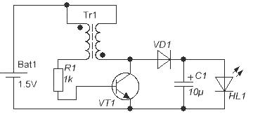
It is easy to see that in this circuit the LED is powered not by pulsating, but DC. Naturally, in this case the brightness of the glow will be slightly higher, and the level of pulsations of the emitted light will be much less. Any high-frequency diode, for example, KD521 (), will be suitable as a diode.
Converters with choke
Another simplest diagram is shown in the figure below. It is somewhat more complicated than the circuit in Figure 1, it contains 2 transistors, but instead of a transformer with two windings it only has inductor L1. Such a choke can be wound on a ring from the same energy-saving lamp, for which you will need to wind only 15 turns of winding wire with a diameter of 0.3...0.5 mm.

With the specified inductor setting on the LED, you can get a voltage of up to 3.8V (forward voltage drop across the 5730 LED is 3.4V), which is enough to power a 1W LED. Setting up the circuit involves selecting the capacitance of capacitor C1 in the range of ±50% of the maximum brightness of the LED. The circuit is operational when the supply voltage is reduced to 0.7V, which ensures maximum use of battery capacity.
If the considered circuit is supplemented with a rectifier on diode D1, a filter on capacitor C1, and a zener diode D2, you will get a low-power power supply that can be used to power op-amp circuits or other electronic components. In this case, the inductance of the inductor is selected within the range of 200...350 μH, diode D1 with a Schottky barrier, zener diode D2 is selected according to the voltage of the supplied circuit.

With a successful combination of circumstances, using such a converter you can obtain an output voltage of 7...12V. If you plan to use the converter to power only LEDs, zener diode D2 can be excluded from the circuit.
All the considered circuits are the simplest voltage sources: limiting the current through the LED is carried out in much the same way as is done in various key fobs or in lighters with LEDs.
The LED, through the power button, without any limiting resistor, is powered by 3...4 small disk batteries, the internal resistance of which limits the current through the LED to a safe level.
Current Feedback Circuits
But an LED is, after all, a current device. It is not for nothing that the documentation for LEDs indicates direct current. Therefore, true LED power circuits contain current feedback: once the current through the LED reaches a certain value, the output stage is disconnected from the power supply.
Voltage stabilizers work exactly the same way, only there is voltage feedback. Below is a circuit for powering LEDs with current feedback.

Upon closer examination, you can see that the basis of the circuit is the same blocking oscillator assembled on transistor VT2. Transistor VT1 is the control one in the feedback circuit. Feedback in this scheme works as follows.
LEDs are powered by voltage that accumulates across an electrolytic capacitor. The capacitor is charged through a diode pulse voltage from the collector of transistor VT2. The rectified voltage is used to power the LEDs.
The current through the LEDs passes along the following path: the positive plate of the capacitor, LEDs with limiting resistors, the current feedback resistor (sensor) Roc, the negative plate of the electrolytic capacitor.
In this case, a voltage drop Uoc=I*Roc is created across the feedback resistor, where I is the current through the LEDs. As the voltage increases (the generator, after all, works and charges the capacitor), the current through the LEDs increases, and, consequently, the voltage across the feedback resistor Roc increases.
When Uoc reaches 0.6V, transistor VT1 opens, closing the base-emitter junction of transistor VT2. Transistor VT2 closes, the blocking generator stops, and stops charging the electrolytic capacitor. Under the influence of a load, the capacitor is discharged, and the voltage across the capacitor drops.
Reducing the voltage on the capacitor leads to a decrease in the current through the LEDs, and, as a result, a decrease in the feedback voltage Uoc. Therefore, transistor VT1 closes and does not interfere with the operation of the blocking generator. The generator starts up and the whole cycle repeats again and again.
By changing the resistance of the feedback resistor, you can vary the current through the LEDs within a wide range. Such circuits are called pulse current stabilizers.
Integral current stabilizers
Currently, current stabilizers for LEDs are produced in an integrated version. Examples include specialized microcircuits ZXLD381, ZXSC300. The circuits shown below are taken from the DataSheet of these chips.

The figure shows the design of the ZXLD381 chip. It contains a PWM generator (Pulse Control), a current sensor (Rsense) and an output transistor. There are only two hanging parts. This LED LED and throttle L1. A typical connection diagram is shown in the following figure. The microcircuit is produced in the SOT23 package. The generation frequency of 350KHz is set by internal capacitors; it cannot be changed. The device efficiency is 85%, starting under load is possible even with a supply voltage of 0.8V.

The forward voltage of the LED should be no more than 3.5V, as indicated in the bottom line under the figure. The current through the LED is controlled by changing the inductance of the inductor, as shown in the table on the right side of the figure. The middle column shows the peak current, the last column shows the average current through the LED. To reduce the level of ripple and increase the brightness of the glow, it is possible to use a rectifier with a filter.

Here we use an LED with a forward voltage of 3.5V, a high-frequency diode D1 with a Schottky barrier, and a capacitor C1 preferably with a low equivalent series resistance (low ESR). These requirements are necessary in order to increase the overall efficiency of the device, heating the diode and capacitor as little as possible. The output current is selected by selecting the inductance of the inductor depending on the power of the LED.
It differs from the ZXLD381 in that it does not have an internal output transistor and a current sensor resistor. This solution allows you to significantly increase the output current of the device, and therefore use a higher power LED.

An external resistor R1 is used as a current sensor, by changing the value of which you can set the required current depending on the type of LED. This resistor is calculated using the formulas given in the datasheet for the ZXSC300 chip. We will not present these formulas here; if necessary, it is easy to find a datasheet and look up the formulas from there. The output current is limited only by the parameters of the output transistor.
When you turn on all the described circuits for the first time, it is advisable to connect the battery through a 10 Ohm resistor. This will help avoid the death of the transistor if, for example, the transformer windings are incorrectly connected. If the LED lights up with this resistor, then the resistor can be removed and further adjustments can be made.
Boris Aladyshkin
LEDs, as sources of optical radiation, have undeniable advantages: small dimensions, high brightness with minimal (units of mA) current, and efficiency.
But due to technological features, they cannot glow at a voltage below 1.6... 1.8 V. This circumstance sharply limits the possibility of using LED emitters in a wide class of devices that have low-voltage power, usually from a single galvanic cell.
Despite the obvious relevance of the problem of low-voltage power supply of LED optical radiation sources, a very limited number of circuit solutions are known in which the authors tried to solve this problem.
In this regard, below is an overview of LED power supply circuits from a low (0.25...1.6 V) voltage source. The variety of circuits presented in this chapter can be reduced to two main types of voltage conversion low level to high. These are circuits with capacitive and inductive energy storage devices [Rk 5/00-23].
Voltage doubler
Figure 1 shows the LED power supply circuit using the principle of doubling the supply voltage. The low-frequency pulse generator is made using transistors of different structures: KT361 and KT315.
The pulse repetition rate is determined by the time constant R1C1, and the duration of the pulses is determined by the time constant R2C1. From the output of the generator, short pulses through resistor R4 are supplied to the base of transistor VT3, the collector circuit of which includes a red LED HL1 (AL307KM) and a germanium diode VD1 of type D9.
A high-capacity electrolytic capacitor C2 is connected between the output of the pulse generator and the connection point between the LED and the germanium diode.
During a long pause between pulses (transistor VT2 is closed and does not conduct current), this capacitor is charged through diode VD1 and resistor R3 to the voltage of the power source. When generating a short pulse, transistor VT2
opens. The negatively charged plate of capacitor C2 is connected to the positive power bus. Diode VD1 is turned off. The charged capacitor C2 is connected in series with the power source.
The total voltage is applied to the LED circuit - the emitter - collector junction of transistor VT3. Since transistor VT3 is unlocked by the same pulse, its emitter-collector resistance becomes small.
Thus, almost double the supply voltage (excluding minor losses) is briefly applied to the LED: a bright flash follows. After this, the process of charging and discharging capacitor C2 is periodically repeated.
Rice. 1. Schematic diagram voltage doubler to power the LED.
Since LEDs can operate at short-term pulse currents tens of times higher than the rated values, the LED does not become damaged.
If it is necessary to increase the reliability of LED emitters with low-voltage power supply and expand the supply voltage range upward, a current-limiting resistor with a resistance of tens or hundreds of Ohms should be connected in series with the LED.
When using an LED of the AL307KM type with a voltage of the beginning of a barely noticeable glow of 1.35... 1.4 V and a voltage at which, without limiting resistance, the current through the LED is 20 mA, 1.6... 1.7 V, the operating voltage of the generator , presented in Figure 1, is 0.8... 1.6 V.
The range limits are determined experimentally in the same way: the lower one indicates the voltage at which the LED begins to glow, the upper one indicates the voltage at which the current consumed by the entire device is approximately 20 mA, i.e. does not exceed in most unfavorable conditions operating current limit through the LED and, at the same time, the converter itself.
As noted earlier, the generator (Figure 1) operates in a pulsed mode, which is, on the one hand, a disadvantage of the circuit, but on the other hand, an advantage, since it allows you to generate bright flashes of light that attract attention.
The generator is quite economical, since the average current consumed by the device is small. At the same time, the circuit must use a low-voltage, but rather bulky, high-capacity electrolytic capacitor (C2).
Simplified version of the voltage converter
Figure 2 shows a simplified version of the generator, which operates similarly to the one described above. The generator, using a small-sized electrolytic capacitor, operates at a supply voltage of 0.9 to 1.6 V.
The average current consumed by the device does not exceed 3 mA at a pulse repetition rate of about 2 Hz. The brightness of the generated flashes of light is slightly lower than in the previous scheme.

Rice. 2. Circuit of a simple low-voltage voltage converter using two transistors from 0.9V to 2V.
Generator using a telephone capsule
The generator shown in Fig. 9.3, uses the TK-67 telephone capsule as a load. This makes it possible to increase the amplitude of the generated pulses and thereby lower the lower limit of the start of generator operation by 200 mV.
By switching to a higher generation frequency, it is possible to continuously “pump” (convert) energy and significantly reduce the capacitance of capacitors.

Rice. 3. Circuit diagram of a low-voltage voltage converter generator using a telephone coil.
Generator with output voltage doubling
Figure 4 shows a generator with an output stage that doubles the output voltage. When transistor VT3 is closed, only a small supply voltage is applied to the LED.
The electrical resistance of the LED is high due to the pronounced nonlinearity of the current-voltage characteristic and is much higher than the resistance of resistor R6. Therefore, capacitor C2 is connected to the power source through resistors R5 and R6.

Rice. 4. Circuit of a low-voltage converter with doubling the output voltage.
Although resistor R6 is used instead of a germanium diode, the principle of operation of the voltage doubler remains the same: charging capacitor C2 with transistor VT3 closed through resistors R5 and R6, followed by connecting the charged capacitor in series with the power source.
When a voltage doubled in this way is applied, the dynamic resistance of the LED at a steeper section of the current-voltage characteristic becomes about 100 Ohms or less for the duration of the capacitor discharge, which is much lower than the resistance of the resistor R6 shunting the capacitor.
The use of resistor R6 instead of a germanium diode allows you to expand the operating range of supply voltages (from 0.8 to 6 V). If there were a germanium diode in the circuit, the device supply voltage would be limited to 1.6...1.8 V.
If the supply voltage were further increased, the current through the LED and germanium diode would increase to an unacceptably high value and irreversible damage would occur.
Converter based on AF generator
In the generator presented in Figure 5, simultaneously with light pulses, ringing pulses of sound frequency are generated. The frequency of sound signals is determined by the parameters of the oscillatory circuit formed by the winding of the telephone capsule and capacitor C2.

Rice. 5. Schematic diagram of a voltage converter for an LED based on an AF generator.
Voltage converters based on multivibrators
LED power supplies based on multivibrators are shown in Figures 6 and 7. The first circuit is based on an asymmetric multivibrator, which, like the devices (Figures 1 - 5), produces short pulses with a long interpulse pause.

Rice. 6. Low-voltage voltage converter based on an asymmetric multivibrator.
Energy storage - electrolytic capacitor SZ is periodically charged from the power source and discharged to the LED, summing its voltage with the supply voltage.
Unlike the previous circuit, the generator (Fig. 7) ensures that the LED glows continuously. The device is based on a symmetrical multivibrator and operates at higher frequencies.

Rice. 7. Converter for powering the LED from a low-voltage source of 0.8 - 1.6V.
In this regard, the capacitance of the capacitors in this circuit is 3...4 orders of magnitude lower. At the same time, the brightness of the glow is noticeably reduced, and the average current consumed by the generator at a power source voltage of 1.5 6 does not exceed 3 mA.
Voltage converters with series connection of transistors

Rice. 8. Voltage converter with series connection of transistors different types conductivity.
The generators shown below in Figures 8 - 13 use a somewhat unusual element as an active element. serial connection transistors of different conductivity types, moreover, covered by positive feedback.

Rice. 9. Two-transistor voltage converter for an LED using a coil from a telephone.
The positive feedback capacitor (Figure 8) simultaneously acts as an energy storage device to obtain a voltage sufficient to power the LED.
A germanium diode (or a resistance replacing it, Fig. 12) is connected parallel to the base-collector transition of transistor VT2 (type KT361).
In a generator with an RC circuit (Fig. 8), due to significant voltage losses on semiconductor junctions, the operating voltage of the device is 1.1... 1.6 V.
It became possible to significantly lower the lower limit of the supply voltage by switching to the LC version of the generator circuit using inductive energy storage devices (Fig. 9 - 13).

Rice. 10. Circuit of a simple low-voltage voltage converter 0.75V -1.5V to 2V based on an LC oscillator.
A telephone capsule is used as an inductive energy storage device in the first circuit (Fig. 9). Simultaneously with the light flashes, the generator produces acoustic signals.
When the capacitor capacity increases to 200 μF, the generator switches to a pulsed economical operating mode, producing intermittent light and sound signals.
The transition to higher operating frequencies is possible through the use of a small-sized inductor with a high quality factor. In this regard, it becomes possible to significantly reduce the volume of the device and lower the lower limit of the supply voltage (Fig. 10 - 13).
The coil of the intermediate frequency circuit from the VEF radio receiver with an inductance of 260 μH was used as inductance. In Fig. 11, 12 show the types of such generators.

Rice. 11. Circuit of a low-voltage voltage converter for an LED with a coil from the IF circuit of the receiver.

Rice. 12. Scheme simple converter voltage for the LED with a coil from the IF circuit of the receiver.
Finally, Figure 13 shows the most simplified version of the device, in which an LED is used instead of an oscillating circuit capacitor.
Capacitor-type voltage converters (with voltage doubling) used to power LED emitters can theoretically reduce the operating supply voltage to only 60% (limit, ideal value — 50%).

Rice. 13. A very simple low voltage voltage converter with an LED on instead of a capacitor.
The use of multistage voltage multipliers for these purposes is unpromising due to progressively increasing losses and a decrease in the efficiency of the converter.
Converters with inductive energy storage are more promising with a further reduction in the operating voltage of the generators that provide operation of the LEDs. At the same time, high efficiency and simplicity of the converter circuit.
Voltage converters of inductive and inductive-capacitive type
Figures 14 - 18 show converters for powering LEDs of inductive and inductive-capacitive type, made on the basis of generators using analogues of an injection field-effect transistor as an active element [Rk 5/00-23].

Rice. 14. Circuit diagram of a low-voltage voltage converter 1-6V to 2V of inductive-capacitive type.
The converter shown in Figure 14 is an inductive-capacitive type device. The pulse generator is made on an analogue of an injection field-effect transistor (transistors VT1 and VT2).
The elements that determine the operating frequency of generation in the audio frequency range are the telephone capsule BF1 (type TK-67), capacitor C1 and resistor R1. Short pulses generated by the generator arrive at the base of transistor VT3, opening it.
At the same time, the charge/discharge of the capacitive energy storage unit (capacitor C2) occurs. When a pulse arrives, the positively charged plate of capacitor C2 is connected to the common bus through transistor VT2, which is open for the duration of the pulse. Diode VD1 closes, transistor VT3 opens.
Thus, a power source and a charged capacitor C2 are connected in series to the load circuit (LED HL1), resulting in a bright flash of the LED.
Transistor VT3 allows you to expand the range of operating voltages of the converter. The device is operational at voltages from 1.0 to 6.0 V. Let us recall that the lower limit corresponds to a barely noticeable glow of the LED, and the upper limit corresponds to the device’s current consumption of 20 mA.
In the region of low voltages (up to 1.45 V), sound generation is not audible, although as the supply voltage subsequently increases, the device begins to produce sound signals, the frequency of which decreases quite quickly.
The transition to higher operating frequencies (Fig. 15) through the use of a high-frequency coil makes it possible to reduce the capacitance of the capacitor that “pumps” energy (capacitor C1).

Rice. 15. Schematic diagram of a low-voltage voltage converter with an HF generator.
A field-effect transistor VT3 (KP103G) is used as a key element that connects the LED to the “positive” power bus for the pulse repetition period. As a result, the operating voltage range of this converter has been expanded to 0.7... 10 V.
Noticeably simplified devices, but operating within a limited range of supply voltages, are shown in Figures 16 and 17. They provide LED illumination in the range of 0.7...1.5 V (at R1=680 Ohm) and 0.69...1, 2 V (at R1=0 Ohm), as well as from 0.68 to 0.82 V (Fig. 17).

Rice. 16. Schematic diagram of a simplified low-voltage voltage converter with an HF generator.

Rice. 17. Simplified low-voltage voltage converter with an RF generator and a telephone capsule as a coil.
The simplest generator is based on an analogue of an injection field-effect transistor (Fig. 18), where the LED simultaneously acts as a capacitor and is the load of the generator. The device operates in a rather narrow range of supply voltages, but the brightness of the LED is quite high, since the converter (Fig. 18) is purely inductive and has high efficiency.

Rice. 18. Low-voltage voltage converter with a generator based on an analogue of an injection field-effect transistor.
The next type of converter is quite well known and is more traditional. These are transformer and autotransformer type converters.
In Fig. Figure 19 shows a transformer-type generator for powering LEDs with low voltage voltage. The generator contains only three elements, one of which is a light-emitting diode.
Without an LED, the device is a simple blocking oscillator, and quite high voltage. If you use an LED as a generator load, it begins to glow brightly even at a low supply voltage (0.6...0.75 V).

Rice. 19. Circuit of a transformer type converter for powering LEDs with low voltage voltage.
In this circuit (Fig. 19), the transformer windings have 20 turns of PEV 0.23 wire. A ferrite ring M1000 (1000NM) K 10x6x2.5 was used as the transformer core. In the absence of generation, the conclusions of one of the transformer windings are as follows! swap.
The converter shown in Figure 20 has the lowest supply voltage of all the devices considered. A significant reduction in the lower limit of the operating voltage was achieved by optimizing the choice of the number (ratio) of winding turns and the method of their inclusion. When using high-frequency germanium transistors such as 1T311, 1T313 (GT311, GT313), such converters begin to operate at a supply voltage above 125 mV.

Rice. 20. Low voltage voltage converter from 0.25V - 0.6V to 2V.

Rice. 21. Experimentally measured characteristics of the generator.
As in the previous circuit, a ferrite ring M1000 (1000NM) K10x6x2.5 was used as the transformer core. The primary winding is made of PEV 0.23 mm wire, the secondary winding is made of PEV 0.33. A fairly bright glow of the LED is observed already at a voltage of 0.3 V.
Figure 21 shows the experimentally measured characteristics of the generator (Fig. 20) when varying the number of turns of the windings. From the analysis of the obtained dependencies it follows that there is an area of optimal ratio between the number of turns of the primary and secondary windings, and with an increase in the number of turns of the primary winding, the minimum operating voltage of the converter gradually decreases, and at the same time the range of operating voltages of the converter narrows.
To solve the inverse problem - expanding the operating voltage range of the converter - an RC circuit can be connected in series with it (Fig. 22).

Rice. 22. Circuit of a low-voltage voltage converter using an RC circuit.
Converter circuits of the inductive or capacitive three-point type
Another type of converter is shown in Figures 23 - 29. Their feature is the use of inductive energy storage devices and circuits made of the “inductive” or “capacitive three-point” type with a barrier mode for turning on the transistor.
The generator (Fig. 23) is operational in the voltage range from 0.66 to 1.55 V. To optimize the operating mode, it is necessary to select the value of resistor R1. As an inductor, as in many previous circuits. an IF filter circuit coil with an inductance of 260 μH was used.

Rice. 23. Voltage converter for LED on one transistor KT315.
Thus, with the number of turns of the primary winding n(1) equal to 50...60 and the number of turns of the secondary winding l(II) - 12, the device is operational in the supply voltage range of 260...440 mV (ratio of the number of turns 50 to 12), and with a ratio of the number of turns of 60 to 12 - 260...415 mV.
When using a ferrite core of a different type or size, this ratio may be disrupted and be different. It is useful to carry out such a study yourself, and present the results in the form of a graph for clarity.
It seems very interesting to use a tunnel diode in the generators under consideration (similar to the one shown in Fig. 20), connected instead of the emitter-base transition of transistor VT1.
The generator (Fig. 24) is slightly different from the previous one (Fig. 23). Its interesting feature is that the brightness of the LED changes with increasing supply voltage (Fig. 25).

Rice. 24. Voltage converter with variable LED brightness.

Rice. 25. Graph of the dependence of the brightness of the LED on the voltage supplying the generator (for Figure 24).
Moreover, the maximum brightness is achieved at 940 mV. The converter shown in Figure 26 can be classified as a three-point generator, with the LED acting as one of the capacitors.
The transformer of the device is made on a ferrite ring (1000HM) K10x6x2.5, and its windings contain approximately 15...20 turns of PELSHO 0.18 wire.

Rice. 26. Low-voltage voltage converter with a three-point generator.
The converter (Fig. 27) differs from the previous one in the LED connection point. The dependence of the brightness of the LED on the supply voltage is shown in Figure 28: as the supply voltage increases, the brightness first increases, then sharply decreases, and then increases again.

Rice. 27. A simple voltage converter for low-voltage power supply of the AL307 LED.

Rice. 28. Dependence of LED brightness on supply voltage.
The simplest circuit for converters of this type is the circuit shown in Figure 29. Installation operating point is achieved by selecting resistor R1.
The LED, as in a number of previous circuits, simultaneously plays the role of a capacitor. As an experiment, it is recommended to connect a capacitor in parallel with the LED and select its capacitance.

Rice. 29. A very simple circuit of a low-voltage voltage converter using one transistor.
Finally
As a general note on setting up the circuits presented above, it should be noted that the supply voltage of all the devices considered, in order to avoid damage to the LEDs, should not (with rare exceptions) exceed 1.6...1.7 V.
Literature: Shustov M.A. Practical circuit design (Book 1).

