29.06.2020
High-quality amplifier without OOS: The End Millennium. The simplest low-frequency amplifiers on transistors ULF power supply from different voltage sources
The proposed amplifier is designed to operate when powered within the range of 0.9-3V to a load with a resistance of 8 ohms. Of course, the power will be about 50 mW, but in many cases this is enough.

The circuit diagram of the low-voltage powered amplifier is shown in the figure above. To test the performance, we assemble the ULF on a breadboard.


ULF consists of input stage on the BC547 transistor and a composite output stage on the BC557, BC547 transistors. Setting the quiescent current of the output stage is carried out using the bias resistor of the base circuit of the input transistor - 220k. Decreasing it increases the quiescent current, increasing it decreases it.

In this amplifier, you can use any low-power silicon transistors that are suitable for conductivity, including KT315-KT361.

But for maximum voltage reduction, it is desirable to use germanium, with low drop voltages. For example, domestic transistors of the MP series or similar imported ones.


Experiments with different power supplies of this amplifier showed that it remains operational even at 0.85 volts! On the ULF diagram, there is a microphone at the input, so if you need to send a signal from another sound source, we put the volume control instead. For testing, a 1-watt dynamic head was connected to the ULF. Of course, the walls did not shake - but you could listen to music :)
Discuss the article POWER AMPLIFIER
Other articles on the construction of this ULF.
Schematic diagram of the power supply.

The power supply is assembled according to one of the standard schemes. A bipolar power supply is selected to power the final amplifiers. This allows the use of low cost, high quality integrated amplifiers and eliminates a number of problems associated with supply voltage ripple and turn-on transients. https://website/
The power supply must provide power to three microcircuits and one LED. Two TDA2030 microcircuits are used as final power amplifiers, and one TDA1524A microcircuit is used as a volume control, stereo base and tone control.
The electrical circuit of the power supply.

|
VD3... VD6 - KD226 |
C1-680mkFx25V C3... C6 - 1000mkFx25V |
On diodes VD3 ... VD6, a bipolar full-wave rectifier with a midpoint is assembled. This switching circuit reduces the voltage drop across the rectifier diodes by half compared to a conventional bridge rectifier, since current flows through only one diode in each half-cycle.
Electrolytic capacitors C3 ... C6 are used as a rectified voltage filter.
On the IC1 chip, a voltage regulator is assembled to power the electronic volume control circuit, stereo base and tone. The stabilizer is assembled according to a standard scheme.
The use of the LM317 chip is due only to the fact that it was available. Here you can apply any integral stabilizer.
The protective diode VD2, indicated by a dotted line, is not necessary when the output voltage on the LM317 chip is below 25 volts. But, if the input voltage of the microcircuit is 25 Volts and higher, and the resistor R3 is trimmer, then it is better to install the diode.
The value of the resistor R3 determines output voltage stabilizer. During prototyping, I soldered a trimmer instead, set the voltage to about 9 volts at the output of the stabilizer with it, and then measured the resistance of this trimmer so that I could install a constant resistor instead.
The rectifier that feeds the stabilizer is made according to a simplified half-wave circuit, which is dictated by purely economic considerations. Four diodes and one capacitor cost more than one diode and one slightly larger capacitor.
The current consumed by the TDA1524A chip is only 35mA, so this scheme is fully justified.
LED HL1 - power-on indicator of the amplifier. A ballast resistor of this indicator is installed on the power supply board - R1 with a nominal resistance of 500 Ohms. The current of the LED depends on the resistance of this resistor. I used a green LED rated at 20mA. When using a red LED type AL307 for a current of 5mA, the resistance of the resistor can be increased by 3-4 times.
Printed circuit board.

The printed circuit board (PCB) is designed based on the design of a particular amplifier and the available electrical components. The board has only one mounting hole, located in the very center of the PCB, which is due to an unusual design.

To increase the cross-section of copper tracks and save ferric chloride, the places free from tracks on the PCB were filled using the "Polygon" tool.
Increasing the width of the tracks also prevents peeling of the foil from the fiberglass in case of violation of the thermal regime or during repeated soldering of radio components.

According to the drawing given above, a printed circuit board was made of foil fiberglass with a cross section of 1 mm.
To connect the wires to the printed circuit board, copper pins (soldiers) were riveted in the holes of the board.
This movie requires Flash Player 9 |
||
And this is the already assembled printed circuit board of the power supply.
To see all six views, drag the picture with the cursor or use the arrow buttons located at the bottom of the picture.
The mesh on the PP copper tracks is the result of using this technology. 
When the board is assembled, it is desirable to test it even before connecting the final amplifiers and the regulator unit. To test the power supply, you need to connect a load equivalent to its outputs, as in the above diagram.
As a load of +12.8 and -12.8 Volt rectifiers, resistors of the PEV-10 type for 10-15 Ohms are suitable.
The voltage at the output of the stabilizer, loaded on a resistor with a resistance of 100-150 ohms, is a good idea to look with an oscilloscope for the absence of ripples when the AC input voltage is reduced from 14.3 to 10 volts.
P.S. Finalization of the printed circuit board.
During commissioning printed circuit board power supply came.

When finalizing, I had to cut one track pos.1 and add one contact pos.2 to connect the transformer winding that feeds the voltage stabilizer.
Low-frequency amplifiers (ULF) are used to convert weak signals of a predominantly audio range into more powerful signals that are acceptable for direct perception through electrodynamic or other sound emitters.
notice, that high frequency amplifiers up to frequencies of 10 ... 100 MHz are built according to similar schemes, the whole difference most often comes down to the fact that the values of the capacitances of the capacitors of such amplifiers decrease as many times as the frequency of the high-frequency signal exceeds the frequency of the low-frequency one.
A simple single transistor amplifier
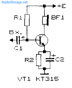
The simplest ULF, made according to the scheme with a common emitter, is shown in Fig. 1. A telephone capsule was used as a load. Permissible voltage power supply for this amplifier 3 ... 12 V.
It is desirable to determine the value of the bias resistor R1 (tens of kΩ) experimentally, since its optimal value depends on the supply voltage of the amplifier, the resistance of the telephone capsule, and the transmission coefficient of a particular instance of the transistor.
Rice. 1. Scheme of a simple ULF on one transistor + capacitor and resistor.
To select the initial value of the resistor R1, it should be taken into account that its value should be about a hundred or more times greater than the resistance included in the load circuit. To select a bias resistor, it is recommended to connect in series a constant resistor with a resistance of 20 ... 30 kOhm and a variable resistor with a resistance of 100 ... 1000 kOhm, after which, applying to the input of the amplifier sound signal small amplitude, for example, from a tape recorder or player, by turning the variable resistor knob to achieve best quality signal at its highest volume.
The value of the capacitance of the transition capacitor C1 (Fig. 1) can be in the range from 1 to 100 microfarads: the greater the value of this capacitance, the lower frequencies the ULF can amplify. To master the technique of amplification low frequencies it is recommended to experiment with the selection of the values of the elements and the operating modes of the amplifiers (Fig. 1 - 4).
Improved Single Transistor Amplifier Options
Complicated and improved in comparison with the scheme in fig. 1 amplifier circuits are shown in fig. 2 and 3. In the diagram in fig. 2 amplification stage additionally contains a chain of frequency-dependent negative feedback(resistor R2 and capacitor C2), which improves the signal quality.
Rice. 2. Scheme of a single-transistor ULF with a chain of frequency-dependent negative feedback.

Rice. 3. A single-transistor amplifier with a divider to supply a bias voltage to the base of the transistor.

Rice. 4. Single transistor amplifier with automatic bias setting for the base of the transistor.
In the diagram in fig. 3, the bias to the base of the transistor is set more “rigidly” using a divider, which improves the quality of the amplifier when its operating conditions change. An “automatic” bias setting based on an amplifying transistor is used in the circuit in fig. 4.
Two-stage transistor amplifier
By connecting in series two simple amplification stages (Fig. 1), you can get a two-stage ULF (Fig. 5). The gain of such an amplifier is equal to the product of the gains of the individual stages. However, it is not easy to obtain a large stable gain with a subsequent increase in the number of stages: the amplifier will most likely self-excite.
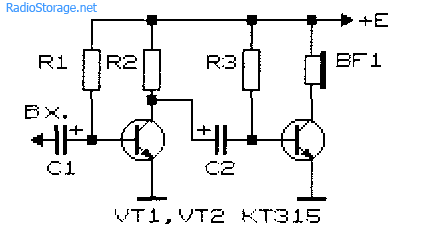
Rice. 5. Scheme of a simple two-stage bass amplifier.
New developments of low-frequency amplifiers, the schemes of which are often given on the pages of magazines recent years, pursue the goal of achieving a minimum coefficient of non-linear distortion, increasing the output power, expanding the bandwidth of amplified frequencies, etc.
At the same time, when setting up various devices and conducting experiments, a simple ULF is often needed, which can be assembled in a few minutes. Such an amplifier should contain a minimum number of deficient elements and operate in a wide range of supply voltage and load resistance.
ULF circuit on field-effect and silicon transistors
A diagram of a simple low-frequency power amplifier with a direct connection between the cascades is shown in fig. 6 [Rl 3/00-14]. The input impedance of the amplifier is determined by the value of the potentiometer R1 and can vary from hundreds of ohms to tens of megohms. The output of the amplifier can be connected to a load with a resistance of 2 ... 4 to 64 ohms and higher.
With a high-resistance load, the KT315 transistor can be used as VT2. The amplifier is operable in the supply voltage range from 3 to 15 V, although its acceptable performance is maintained even when the supply voltage drops down to 0.6 V.
Capacitor C1 can be selected from 1 to 100 microfarads. In the latter case (C1 \u003d 100 μF), the ULF can operate in the frequency band from 50 Hz to 200 kHz and above.

Rice. 6. Scheme of a simple low-frequency amplifier on two transistors.
The amplitude of the ULF input signal should not exceed 0.5 ... 0.7 V. The output power of the amplifier can vary from tens of mW to units of W, depending on the load resistance and the magnitude of the supply voltage.
Setting up the amplifier consists in selecting resistors R2 and R3. With their help, the voltage at the drain of the transistor VT1 is set, equal to 50 ... 60% of the voltage of the power source. Transistor VT2 must be installed on a heat sink plate (radiator).
Track-cascade ULF with direct connection
On fig. 7 shows a diagram of another outwardly simple ULF with direct connections between the cascades. This kind of connection improves the frequency response of the amplifier in the low-frequency region, the circuit as a whole is simplified.

Rice. 7. Schematic diagram of a three-stage ULF with a direct connection between the stages.
At the same time, the tuning of the amplifier is complicated by the fact that each amplifier resistance has to be selected in individually. Roughly, the ratio of resistors R2 and R3, R3 and R4, R4 and R BF should be within (30 ... 50) to 1. Resistor R1 should be 0.1 ... 2 kOhm. The calculation of the amplifier shown in fig. 7 can be found in the literature, eg [P 9/70-60].
Schemes of cascade ULF on bipolar transistors
On fig. 8 and 9 show cascode ULF circuits on bipolar transistors. Such amplifiers have a rather high gain Ku. The amplifier in fig. 8 has Ku=5 in the frequency band from 30 Hz to 120 kHz [MK 2/86-15]. ULF according to the scheme in Fig. 9 with a harmonic coefficient of less than 1% has a gain of 100 [RL 3/99-10].

Rice. 8. Cascade ULF on two transistors with gain = 5.

Rice. 9. Cascade ULF on two transistors with gain = 100.
Economical ULF on three transistors
For portable electronic equipment, an important parameter is the efficiency of VLF. The scheme of such a ULF is shown in fig. 10 [RL 3/00-14]. Here we used the cascade connection of the field effect transistor VT1 and bipolar transistor VT3, and the transistor VT2 is turned on in such a way that it stabilizes the operating point of VT1 and VT3.
With an increase in the input voltage, this transistor shunts the emitter-base VT3 junction and reduces the value of the current flowing through the transistors VT1 and VT3.

Rice. 10. Scheme of a simple economical low-frequency amplifier on three transistors.
As in the above circuit (see Fig. 6), the input impedance of this ULF can be set in the range from tens of ohms to tens of megohms. A telephone primer, for example, TK-67 or TM-2V, was used as a load. A telephone capsule connected with a plug can simultaneously serve as a power switch for the circuit.
The ULF supply voltage ranges from 1.5 to 15 V, although the device remains operational even when the supply voltage drops to 0.6 V. In the supply voltage range of 2 ... 15 V, the current consumed by the amplifier is described by the expression:
1(µA) = 52 + 13*(Upit)*(Upit),
where Upit is the supply voltage in Volts (V).
If you turn off the transistor VT2, the current consumed by the device increases by an order of magnitude.
Two-cascade ULF with direct connection between the cascades
Examples of ULF with direct connections and a minimum selection of the operating mode are the circuits shown in Fig. 11 - 14. They have high gain and good stability.

Rice. 11. A simple two-stage ULF for a microphone (low noise level, high gain).

Rice. 12. Two-stage low-frequency amplifier based on KT315 transistors.

Rice. 13. Two-stage low-frequency amplifier based on KT315 transistors - option 2.
The microphone amplifier (Fig. 11) is characterized low level intrinsic noise and high gain [MK 5/83-XIV]. An electrodynamic type microphone was used as the BM1 microphone.
A telephone capsule can also act as a microphone. Stabilization operating point(initial bias based on the input transistor) amplifiers in fig. 11 - 13 is carried out due to the voltage drop across the emitter resistance of the second amplification stage.

Rice. 14. Two-stage ULF with a field-effect transistor.
The amplifier (Fig. 14), which has a high input resistance (about 1 MΩ), is made on a field-effect transistor VT1 (source follower) and bipolar - VT2 (with a common one).
Cascade low frequency amplifier on field effect transistors, which also has a high input impedance, is shown in Fig. 15.

Rice. 15. diagram of a simple two-stage ULF on two field-effect transistors.
ULF circuits for working with low-ohm load
Typical ULF, designed to operate on a low-resistance load and having an output power of tens of mW or more, are shown in Fig. 16, 17.

Rice. 16. Simple ULF for low impedance load switching operation.
Electrodynamic head BA1 can be connected to the output of the amplifier, as shown in fig. 16, or in the diagonal of the bridge (Fig. 17). If the power source is made of two batteries (accumulators) connected in series, the output of the BA1 head, right according to the diagram, can be connected to their midpoint directly, without capacitors C3, C4.

Rice. 17. Low-frequency amplifier circuit with the inclusion of a low-resistance load in the diagonal of the bridge.
If you need a circuit for a simple tube ULF, then such an amplifier can be assembled even on a single tube, see our electronics website in the appropriate section.
Literature: Shustov M.A. Practical Circuitry (Book 1), 2003.
Corrections in the post: in fig. 16 and 17 instead of the diode D9, a chain of diodes is installed.
Making a good power supply for a power amplifier (VLF) or other electronic device is a very important task. The quality and stability of the entire device depends on what the power source will be.
In this publication I will talk about the manufacture of a simple transformer power supply for my homemade amplifier low frequency power "Phoenix P-400".
Such, not complex block power supply can be used to power various low frequency power amplifier circuits.
Foreword
For the future power supply unit (PSU) to the amplifier, I already had a toroidal core with a wound primary winding of ~ 220V, so the task of choosing a "pulse PSU or based on a network transformer" was not.
At impulse sources small size and weight, high output power and high efficiency. Power supply based on a network transformer - has big weight, easy to manufacture and set up, and also do not have to deal with dangerous voltages when setting up the circuit, which is especially important for beginners like me.
toroidal transformer
Toroidal transformers, in comparison with transformers on armored cores made of Ш-shaped plates, have several advantages:
- smaller volume and weight;
- higher efficiency;
- best cooling for windings.
The primary winding already contained approximately 800 turns of 0.8 mm PELSHO wire, it was filled with paraffin and insulated with a layer of thin PTFE tape.
By measuring the approximate dimensions of the transformer iron, you can calculate its overall power, so you can figure out whether the core is suitable for obtaining required power or not.

Rice. 1. Dimensions of the iron core for a toroidal transformer.
- Overall power (W) \u003d Window area (cm 2) * Cross-sectional area (cm 2)
- Window area = 3.14 * (d/2) 2
- Cross-sectional area \u003d h * ((D-d) / 2)
For example, let's calculate a transformer with iron dimensions: D=14cm, d=5cm, h=5cm.
- Window area \u003d 3.14 * (5cm / 2) * (5cm / 2) \u003d 19.625 cm 2
- Sectional area \u003d 5cm * ((14cm-5cm) / 2) \u003d 22.5 cm 2
- Overall power = 19.625 * 22.5 = 441 watts.
The overall power of the transformer I used turned out to be clearly less than I expected - somewhere around 250 watts.
Selection of voltages for secondary windings
Knowing the required voltage at the output of the rectifier after the electrolytic capacitors, it is possible to approximately calculate the required voltage at the output of the secondary winding of the transformer.
Numeric value constant voltage after the diode bridge and smoothing capacitors will increase by about 1.3..1.4 times, compared with the alternating voltage supplied to the input of such a rectifier.
In my case, to power the UMZCH, you need a bipolar constant voltage - 35 volts on each arm. Accordingly, each secondary winding must have AC voltage: 35 Volts / 1.4 = ~25 Volts.
By the same principle, I made an approximate calculation of the voltage values \u200b\u200bfor other secondary windings of the transformer.
Calculation of the number of turns and winding
To power the remaining electronic components of the amplifier, it was decided to wind several separate secondary windings. A wooden shuttle was made for winding coils with copper enameled wire. It can also be made from fiberglass or plastic.
Rice. 2. Shuttle for winding a toroidal transformer.
The winding was carried out with copper enameled wire, which was available:
- for 4 UMZCH power windings - a wire with a diameter of 1.5 mm;
- for other windings - 0.6 mm.
I selected the number of turns for the secondary windings experimentally, since I did not know exact amount turns of the primary winding.
The essence of the method:
- We wind 20 turns of any wire;
- We connect the primary winding of the transformer to the network ~ 220V and measure the voltage on the wound 20 turns;
- We divide the required voltage by that obtained from 20 turns - we find out how many times 20 turns are needed for winding.
For example: we need 25V, and out of 20 turns we get 5V, 25V / 5V = 5 - we need to wind 20 turns 5 times, that is, 100 turns.
The calculation of the length of the required wire was performed as follows: I wound 20 turns of wire, made a mark on it with a marker, unwound it and measured its length. I divided the required number of turns by 20, multiplied the resulting value by the length of 20 turns of wire - I got approximately the required length of wire for winding. By adding 1-2 meters of stock to the total length, you can wind the wire on the shuttle and safely cut it off.
For example: you need 100 turns of wire, the length of 20 wound turns turned out to be 1.3 meters, we find out how many times 1.3 meters need to be wound to get 100 turns - 100/20 = 5, we find out the total length of the wire (5 pieces of 1.3 m each) - 1.3 * 5 = 6.5 m. We add 1.5m for the stock and get the length - 8m.
For each subsequent winding, the measurement should be repeated, since with each new winding the length of wire required per turn will increase.
To wind each pair of windings of 25 volts, two wires were laid in parallel on the shuttle at once (for 2 windings). After winding, the end of the first winding is connected to the beginning of the second - we got two secondary windings for a bipolar rectifier with a connection in the middle.
After winding each of the pairs of secondary windings to power the UMZCH circuits, they were insulated with a thin fluoroplastic tape.
Thus, 6 secondary windings were wound: four for powering the UMZCH and two more for power supplies for the rest of the electronics.
Scheme of rectifiers and voltage stabilizers
Below is a schematic diagram of the power supply for my homemade power amplifier.

Rice. 2. Schematic diagram of the power supply for a homemade bass power amplifier.
To power the low-frequency power amplifier circuits, two bipolar rectifiers are used - A1.1 and A1.2. Rest electronic blocks amplifier will be powered by voltage regulators A2.1 and A2.2.
Resistors R1 and R2 are needed to discharge electrolytic capacitors when the power lines are disconnected from the power amplifier circuits.
There are 4 amplification channels in my UMZCH, they can be turned on and off in pairs using switches that switch the power lines of the UMZCH scarf using electromagnetic relays.
Resistors R1 and R2 can be excluded from the circuit if the power supply is constantly connected to the UMZCH boards, in which case the electrolytic capacities will be discharged through the UMZCH circuit.
Diodes KD213 are designed for a maximum forward current of 10A, in my case this is enough. The diode bridge D5 is designed for a current of at least 2-3A, it was assembled from 4 diodes. C5 and C6 are capacitances, each of which consists of two 10,000 microfarad capacitors at 63V.

Rice. 3. Schematic diagrams DC voltage stabilizers on L7805, L7812, LM317 microcircuits.
Deciphering the names on the diagram:
- STAB - voltage regulator without adjustment, current not more than 1A;
- STAB+REG - adjustable voltage regulator, current not more than 1A;
- STAB+POW - adjustable voltage stabilizer, current approximately 2-3A.
When using LM317, 7805 and 7812 microcircuits, the output voltage of the stabilizer can be calculated using a simplified formula:
Uout = Vxx * (1 + R2/R1)
Vxx for chips has the following meanings:
- LM317 - 1.25;
- 7805 - 5;
- 7812 - 12.
Calculation example for LM317: R1=240R, R2=1200R, Uout = 1.25*(1+1200/240) = 7.5V.
Design
Here's how it was planned to use the voltage from the power supply:
- +36V, -36V - power amplifiers on TDA7250
- 12V - electronic volume controls, stereo processors, output power indicators, thermal control circuits, fans, backlight;
- 5V - temperature indicators, microcontroller, digital control panel.
The voltage regulator chips and transistors were mounted on small heatsinks that I removed from non-working computer power supplies. The cases were attached to the radiators through insulating gaskets.
The printed circuit board was made of two parts, each of which contains a bipolar rectifier for the UMZCH circuit and the required set of voltage stabilizers.

Rice. 4. One half of the power supply board.

Rice. 5. The other half of the power supply board.
![]()
Rice. 6. Ready-made power supply components for a homemade power amplifier.
Later, during debugging, I came to the conclusion that it would be much more convenient to make voltage stabilizers on separate boards. Nevertheless, the "all on one board" option is also not bad and convenient in its own way.
Also, a rectifier for UMZCH (diagram in Figure 2) can be assembled by surface mounting, and stabilizer circuits (Figure 3) in the required quantity - on separate printed circuit boards.
The connection of the electronic components of the rectifier is shown in Figure 7.

Rice. 7. Connection diagram for assembling a bipolar rectifier -36V + 36V using surface mounting.
Connections must be made using thick insulated copper conductors.
The diode bridge with 1000pF capacitors can be placed separately on the heatsink. Mounting of powerful KD213 diodes (tablets) on one common radiator must be carried out through insulating thermal pads (thermoresin or mica), since one of the diode leads has contact with its metal lining!
For the filtering circuit (electrolytic capacitors of 10000uF, resistors and ceramic capacitors of 0.1-0.33uF), you can use hastily assemble a small panel - a printed circuit board (Figure 8).

Rice. 8. An example of a panel with slots made of fiberglass for mounting rectifier smoothing filters.
To make such a panel, you need a rectangular piece of fiberglass. Using a homemade cutter (Figure 9), made from a hacksaw blade for metal, we cut the copper foil along the entire length, then we cut one of the resulting parts in half perpendicularly.

Rice. 9. Homemade cutter from a hacksaw blade, made on a grinder.
After that, we outline and drill holes for parts and fasteners, clean the copper surface with thin sandpaper and tin it with flux and solder. We solder the parts and connect to the circuit.
Conclusion
Here is such an uncomplicated power supply was made for a future homemade power amplifier audio frequency. It remains to supplement it with a soft start circuit and a standby mode.
UPD: Yuri Glushnev sent a printed circuit board for assembling two stabilizers with voltages + 22V and + 12V. It contains two STAB + POW circuits (Fig. 3) on LM317, 7812 microcircuits and TIP42 transistors.

Rice. 10. Printed circuit board of voltage stabilizers for + 22V and + 12V.
Download - (63 KB).
Another PCB designed for the STAB + REG adjustable voltage regulator circuit based on the LM317:

Rice. 11. Printed circuit board for an adjustable voltage regulator based on the LM317 chip.
They are a thing of the past, and now, in order to assemble any simple amplifier, you no longer have to suffer with calculations and rivet a large printed circuit board.
Now almost all cheap amplifying equipment is made on microcircuits. The most widely used TDA chips for amplifying the audio signal. These are currently used in car radios, active subwoofers, home acoustics, and many other audio amplifiers, and look something like this:


Pros of TDA chips
- In order to assemble an amplifier on them, it is enough to supply power, connect speakers and several radio elements.
- The dimensions of these microcircuits are quite small, but they will need to be placed on a radiator, otherwise they will get very hot.
- They are sold at any radio store. On Ali, something is expensive, if you take it at retail.
- They have built-in various protections and other options, such as mute and so on. But according to my observations, the protections do not work very well, so the microcircuits often die either from overheating or from. So it is advisable not to close the microcircuit pins to each other and not to overheat the microcircuit, squeezing all the juice out of it.
- Price. I wouldn't say they are very expensive. For the price and functions they perform, they have no equal.
Single-channel amplifier on TDA7396
Let's assemble a simple single-channel amplifier on the TDA7396 chip. At the time of this writing, I took it at a price of 240 rubles. The datasheet for the microcircuit said that this microcircuit can deliver up to 45 watts into a 2 ohm load. That is, if you measure the resistance of the speaker coil and it will be about 2 ohms, then it is quite possible to get a peak power of 45 watts on the speaker.This power is quite enough to arrange a disco in the room not only for yourself, but also for your neighbors and at the same time get a mediocre sound, which, of course, cannot be compared with hi-fi amplifiers.
Here is the pinout of the chip:

We will assemble our amplifier according to the typical scheme that was attached in the datasheet itself:

We feed +Vs to leg 8, and we don’t feed anything to leg 4. So the diagram will look like this:

Vs is the supply voltage. It can be from 8 to 18 volts. “IN+” and “IN-” - here we give a weak sound signal. We hook the speaker to the 5th and 7th legs. We put the sixth leg on the minus.
Here is my flush mount build

I did not use capacitors at the 100nF and 1000uF power input, since I have pure voltage coming from the power supply.
Rocked the speaker with the following parameters:

As you can see, the resistance of the coil is 4 ohms. The frequency band indicates that it is a subwoofer type.
And this is what my sub looks like in a self-made case:

I tried to shoot a video, but the sound on the video is very bad for me. But still, I can say that from the phone at medium power it was already pecking so that the ears were wrapped, although the consumption of the entire circuit in working form was only about 10 watts (we multiply 14.3 by 0.73). In this example, I took the voltage, as in a car, that is, 14.4 Volts, which fits well into our operating range from 8 to 18 Volts.

If you do not have a powerful power source, then it can be assembled according to this scheme.
Do not go in cycles in this chip. These TDA chips, as I said, there are many types. Some of them amplify the stereo signal and can output sound to 4 speakers at once, as is done in car radios. So do not be lazy to rummage through the Internet and find a suitable TDA. After completing the assembly, let your neighbors check out your amplifier by unscrewing the volume knob for the entire balalaika and leaning the powerful speaker against the wall).
But in the article I assembled an amplifier on a TDA2030A chip

It turned out very well, since the TDA2030A has the best performance than TDA7396
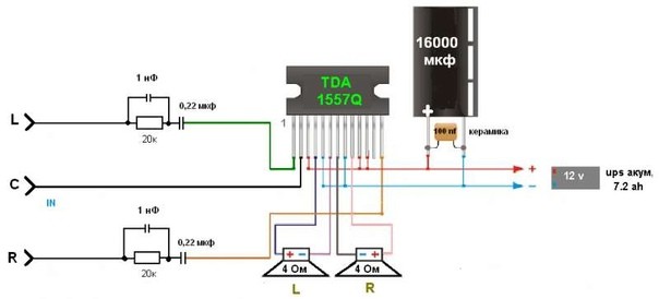
I will also add, for a change, another circuit from a subscriber whose amplifier on the TDA 1557Q has been working properly for more than 10 years in a row:
Amplifiers on Aliexpress
On Ali, I also found kit kits on TDA. For example, this stereo amplifier is 15 watts per channel and costs $1. This power is enough to hang out with your favorite tracks in the little room

You can buy.
And here he's ready right now

Anyway, there are a lot of these amplifier modules on Aliexpress. Click on this link and choose any amplifier you like.

