29.06.2020
Driver for car LEDs. Free homemade driver for powering LEDs from an electronic converter for energy-saving lamps. LEDs for LED drivers
Let's consider ways to connect medium-power ice diodes to the most popular ratings of 5V, 12 volts, 220V. Then they can be used in the manufacture of color and music devices, signal level indicators, smooth switching on and off. I’ve been planning to make a smooth artificial dawn for a long time in order to maintain my daily routine. In addition, dawn emulation allows you to wake up much better and easier.
Drivers with power supply from 5V to 30V

If you have a suitable power source from any household appliances, then it is better to use a low-voltage driver to turn it on. They can be up or down. A booster will make even 1.5V 5V so that the LED circuit works. A step-down from 10V-30V will make a lower one, for example 15V.
They are sold in a large assortment by the Chinese; the low-voltage driver differs in two regulators from simple stabilizer Volt.
The actual power of such a stabilizer will be lower than what the Chinese indicated. In the module parameters, they write the characteristics of the microcircuit and not the entire structure. If there is a large radiator, then such a module will handle 70% - 80% of what was promised. If there is no radiator, then 25% - 35%.

Particularly popular are models based on LM2596, which are already quite outdated due to low efficiency. They also get very hot, so without a cooling system they do not hold more than 1 Ampere.
XL4015, XL4005 are more efficient, the efficiency is much higher. Without a cooling radiator, they can withstand up to 2.5A. There are absolutely miniature models on MP1584 measuring 22mm by 17mm.
Turn on 1 diode

The most commonly used are 12 volts, 220 volts and 5V. This is how a low-power LED lights wall switches for 220V. Factory standard switches most often have a neon lamp installed.
Parallel connection

When connecting in parallel, it is advisable to use a separate resistor for each series circuit of diodes in order to obtain maximum reliability. Another option is to put one powerful resistor on several LEDs. But if one LED fails, the current on the remaining ones will increase. By whole it will be higher than the nominal or specified value, which will significantly reduce the resource and increase heating.
The rationality of using each method is calculated based on the requirements for the product.
Serial connection

Serial connection when powered from 220V is used in filament diodes and LED strips at 220 volts. In a long chain of 60-70 LEDs, each drops 3V, which allows you to connect directly to high voltage. Additionally, only a current rectifier is used to obtain plus and minus.
This connection is used in any lighting technology:
- LED lamps for home;
- led lamps;
- New Year's garlands for 220V;
- LED strips 220.
Lamps for the home usually use up to 20 LEDs connected in series; the voltage across them is about 60V. Maximum amount used in Chinese corn light bulbs, from 30 to 120 LED pieces. Corns do not have a protective flask, so the electrical contacts on which up to 180V are completely open.
Be careful if you see a long series string, and they are not always grounded. My neighbor grabbed the corn with bare hands and then recited fascinating poems from bad words.
RGB LED connection

Low-power three-color RGB LEDs consist of three independent crystals located in one housing. If 3 crystals (red, green, blue) are turned on simultaneously, we get white light.
Each color is controlled independently of the others using an RGB controller. The control unit has ready-made programs and manual modes.
Turning on COB diodes

The connection diagrams are the same as for single-chip and three-color LEDs SMD5050, SMD 5630, SMD 5730. The only difference is that instead of 1 diode, a series circuit of several crystals is included.
Powerful LED matrices contain many crystals connected in series and in parallel. Therefore, power is required from 9 to 40 volts, depending on the power.
Connecting SMD5050 for 3 crystals

The SMD5050 differs from conventional diodes in that it consists of 3 white light crystals, and therefore has 6 legs. That is, it is equal to three SMD2835 made on the same crystals.
When connected in parallel using one resistor, reliability will be lower. If one of the crystals fails, the current through the remaining 2 increases. This leads to accelerated burnout of the remaining ones.
By using a separate resistance for each crystal, the above disadvantage is eliminated. But at the same time, the number of resistors used increases by 3 times and the LED connection circuit becomes more complex. Therefore, it is not used in LED strips and lamps.

LED strip 12V SMD5630

A clear example connecting an LED to 12 volts is an LED strip. It consists of sections of 3 diodes and 1 resistor connected in series. Therefore, it can only be cut in the indicated places between these sections.

LED strip RGB 12V SMD5050

RGB tape uses three colors, each is controlled separately, and a resistor is installed for each color. You can cut only at the indicated location, so that each section has 3 SMD5050 and can be connected to 12 volts.

Powerful LEDs in lighting devices are connected through electronic drivers that stabilize the current at their output.
Nowadays, so-called energy-saving fluorescent lamps (compact fluorescent lamps - CFLs) have become widespread. But over time, they fail. One of the causes of the malfunction is burnout of the lamp filament. Do not rush to dispose of such lamps because the electronic board contains many components that can be used in the future in other homemade devices. These are chokes, transistors, diodes, capacitors. Typically, these lamps have a functional electronic board, which makes it possible to use them as a power supply or driver for an LED. As a result, in this way we will get a free driver for connecting LEDs, which is even more interesting.
You can watch the process of making homemade products in the video:
List of tools and materials
-energy saving fluorescent lamp;
-screwdriver;
- soldering iron;
-tester;
-white LED 10W;
-enamel wire with a diameter of 0.4 mm;
-thermal paste;
- diodes of the HER, FR, UF brand for 1-2A
-desk lamp.
Step one. Disassembling the lamp.
We disassemble the energy-saving fluorescent lamp by carefully prying it off with a screwdriver. The lamp bulb cannot be broken as there is mercury vapor inside. We call the filament of the bulb with a tester. If at least one thread shows a break, then the bulb is faulty. If there is a working similar lamp, then you can connect the bulb from it to the electronic board being converted to make sure that it is working properly.

Step two. Remaking the electronic converter.
For the modification, I used a 20W lamp, the choke of which can withstand a load of up to 20 W. For a 10W LED this is enough. If you need to connect a more powerful load, you can use an electronic lamp converter board with the appropriate power, or change the inductor with the core bigger size.
It is also possible to power LEDs of lower power by selecting the required voltage by the number of turns on the inductor.
I mounted wire jumpers on the pins to connect the lamp filaments.


20 turns of enamel wire need to be wound over the primary winding of the inductor. Then we solder the secondary wound winding to the rectifier diode bridge. We connect 220V voltage to the lamp and measure the voltage at the output from the rectifier. It was 9.7V. An LED connected through an ammeter consumes a current of 0.83A. This LED has a rated current of 900mA, but in order to increase its service life, the current consumption is specially reduced. The diode bridge can be assembled on the board by surface mounting.
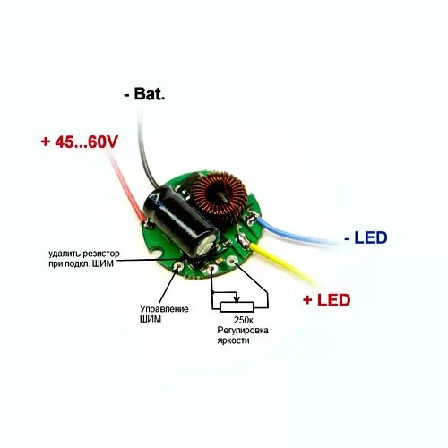
Diagram of the converted electronic converter board. As a result, from the inductor we get a transformer with a connected rectifier. Green the added components are shown.

Step three. Assembling an LED table lamp.
We remove the 220 volt lamp socket. I installed a 10W LED using thermal paste on a metal lampshade of an old table lamp. The table lamp shade serves as a heat sink for the LED.

The electronic power board and diode bridge were placed in the housing of the table lamp stand.
Probably everyone, even a novice radio amateur, knows that in order to connect a regular LED to a power source, you only need one resistor. But what if the LED is powerful? Watt so 10. What to do then?
I'll show you a way to make a simple driver for a high-power LED using just two components.
For the stabilizer driver we need:
1. Resistor – .
2. Microcircuit – LM317 – .

LM317 is a stabilizer chip. Great for designing regulated power supplies or drivers to power LEDs, as in our case.

Advantages of LM317
- The voltage stabilization range is from 1.7 (including LED voltage - 3 V) to 37 V. An excellent characteristic for motorists: the brightness will not fluctuate at any speed;
- Output current up to 1.5, you can connect several powerful LEDs;
The stabilizer has a built-in overheating protection system and short circuit. - The negative power of the LED in the switching circuit is taken from the power source, so when attached to the car body, the number of mounting wires is reduced, and the body can act as a large heat sink for the LED.
Driver circuit for high power LED

I will connect a 3 Watt LED. As a result, we will need to calculate the resistance for our LED. A 1 W LED consumes 350 mA, and a 3 W LED consumes 700 mA (you can see it in the datasheet). The LM317 microcircuit has a stabilizer reference voltage of 1.25 - this number is constant. It needs to be divided by the current and you get the resistance of the resistor. That is: 1.25 / 0.7 = 1.78 Ohm. We take the current in amperes. We select the closest resistor in terms of resistance, since there are no resistors with a resistance of 1.78. We take 1.8 and assemble the circuit.
If the power of your LED exceeds 1 W, then the chip must be installed on a radiator. In general, LM317 is designed for current up to 1.5.
Our circuit can be powered with voltage from 3 to 37 volts. Agree, a solid range of nutrition is obtained. But the higher the voltage, the more the microcircuit heats up, keep this in mind.

The use of LEDs as lighting sources usually requires specialized driver. But it happens that the necessary driver is not at hand, but you need to organize lighting, for example, in a car, or test the LED for brightness. In this case, you can do it yourself for LEDs.
How to make a driver for LEDs
The circuits below use the most common elements that can be purchased at any radio store. No special equipment is required for assembly - everything necessary tools are widely available. Despite this, with a careful approach, the devices work for quite a long time and are not much inferior to commercial samples.
Required materials and tools
In order to assemble a homemade driver, you will need:
- Soldering iron with a power of 25-40 W. You can use more power, but this increases the risk of overheating of the elements and their failure. It is best to use a soldering iron with a ceramic heater and a non-burning tip, because... a regular copper tip oxidizes quite quickly and has to be cleaned.
- Flux for soldering (rosin, glycerin, FKET, etc.). It is advisable to use a neutral flux, in contrast to active fluxes (orthophosphorus and hydrochloric acid, zinc chloride, etc.), it does not oxidize contacts over time and is less toxic. Regardless of the flux used, after assembling the device, it is better to wash it with alcohol. For active fluxes this procedure is mandatory, for neutral ones - to a lesser extent.
- Solder. The most common is low-melting tin-lead solder POS-61. Lead-free solders are less harmful if fumes are inhaled during soldering, but have more high temperature melting with less fluidity and a tendency for the seam to degrade over time.
- Small pliers for bending leads.
- Wire cutters or side cutters for cutting long ends of leads and wires.
- Installation wires are insulated. Stranded copper wires with a cross-section of 0.35 to 1 mm2 are best suited.
- Multimeter for monitoring voltage at nodal points.
- Electrical tape or heat shrink tubing.
- A small prototype board made of fiberglass. A board measuring 60x40 mm will be sufficient.

PCB development board for quick installation
Simple driver circuit for 1 W LED
One of the simplest circuits for powering a powerful LED is shown in the figure below:

As you can see, in addition to the LED, it includes only 4 elements: 2 transistors and 2 resistors.
The powerful n-channel field-effect transistor VT2 acts here as a regulator of the current passing through the LED. Resistor R2 determines the maximum current passing through the LED and also acts as a current sensor for transistor VT1 in the feedback circuit.
The more current passes through VT2, the greater the voltage drops across R2, accordingly VT1 opens and lowers the voltage at the gate of VT2, thereby reducing the LED current. In this way, stabilization of the output current is achieved.
The circuit is powered from a source DC voltage 9 - 12 V, current not less than 500 mA. The input voltage should be at least 1-2 V greater than the voltage drop across the LED.
Resistor R2 should dissipate 1-2 W of power, depending on the required current and supply voltage. Transistor VT2 is n-channel, designed for a current of at least 500 mA: IRF530, IRFZ48, IRFZ44N. VT1 – any low-power bipolar npn: 2N3904, 2N5088, 2N2222, BC547, etc. R1 - power 0.125 - 0.25 W with a resistance of 100 kOhm.
Due to the small number of elements, assembly can be carried out by hanging installation:

Another one simple circuit drivers based on linear controlled voltage stabilizer LM317:

Here the input voltage can be up to 35 V. The resistor resistance can be calculated using the formula:
where I is the current strength in amperes.
In this circuit, the LM317 will dissipate significant power when big difference between the supply voltage and the drop across the LED. Therefore, it will have to be placed on a small one. The resistor must also be rated for at least 2 W.
This scheme is discussed more clearly in the following video:
Here's how to connect powerful LED, using batteries with a voltage of about 8 V. When the voltage drop across the LED is about 6 V, the difference is small, and the microcircuit does not heat up much, so you can do without a radiator.
Please note that if there is a large difference between the supply voltage and the drop across the LED, it is necessary to place the microcircuit on a heat sink.
Power driver circuit with PWM input
Below is a circuit for powering high-power LEDs:

The driver is built on a dual comparator LM393. The circuit itself is a buck-converter, that is, a pulse step-down voltage converter.
Driver Features
- Supply voltage: 5 - 24 V, constant;
- Output current: up to 1 A, adjustable;
- Output power: up to 18 W;
- Output short circuit protection;
- The ability to control brightness using an external PWM signal (it will be interesting to read how).
Operating principle
Resistor R1 with diode D1 form a source of reference voltage of about 0.7 V, which is additionally regulated by variable resistor VR1. Resistors R10 and R11 serve as current sensors for the comparator. As soon as the voltage across them exceeds the reference one, the comparator will close, thus closing the pair of transistors Q1 and Q2, and they, in turn, will close the transistor Q3. However, inductor L1 at this moment tends to resume the flow of current, so the current will flow until the voltage at R10 and R11 becomes less than the reference voltage, and the comparator opens transistor Q3 again.
The pair of Q1 and Q2 acts as a buffer between the output of the comparator and the gate of Q3. This protects the circuit from false positives due to interference on the Q3 gate, and stabilizes its operation.
The second part of the comparator (IC1 2/2) is used for additional brightness control using PWM. To do this, the control signal is applied to the PWM input: when TTL logic levels (+5 and 0 V) are applied, the circuit will open and close Q3. The maximum signal frequency at the PWM input is about 2 KHz. This input can also be used to turn the device on and off using the remote control.
D3 is a Schottky diode rated for currents up to 1 A. If you cannot find a Schottky diode, you can use a pulse diode, for example FR107, but output power then it will decrease somewhat.
The maximum output current is adjusted by selecting R2 and turning on or off R11. This way you can get the following values:
- 350 mA (1 W LED): R2=10K, R11 disabled,
- 700 mA (3 W): R2=10K, R11 connected, nominal 1 Ohm,
- 1A (5W): R2=2.7K, R11 connected, nominal 1 Ohm.
Within narrower limits, adjustment is made using a variable resistor and a PWM signal.
Assembling and configuring the driver
Driver components are installed on breadboard. First, the LM393 chip is installed, then the smallest components: capacitors, resistors, diodes. Then transistors are installed, and lastly a variable resistor.
It is better to place elements on the board in such a way as to minimize the distance between the connected pins and use as few wires as jumpers as possible.
When connecting, it is important to observe the polarity of the diodes and the pinout of the transistors, which can be found in technical description on these components. Diodes can also be used in resistance measurement mode: in the forward direction, the device will show a value of the order of 500-600 Ohms.
To power the circuit, you can use an external DC voltage source of 5-24 V or batteries. 6F22 (“crown”) and other batteries have too small a capacity, so their use is impractical when using high-power LEDs.
After assembly, you need to adjust the output current. To do this, LEDs are soldered to the output, and the VR1 engine is set to the lowest position according to the diagram (checked with a multimeter in the “testing” mode). Next, we apply the supply voltage to the input, and by rotating the VR1 knob we achieve the required brightness.
List of elements:

Conclusion
The first two of the considered circuits are very simple to manufacture, but they do not provide short circuit protection and have rather low efficiency. For long-term use, the third circuit on LM393 is recommended, since it does not have these disadvantages and has greater capabilities for adjusting the output power.
must be connected to the power supply through special devices that stabilize the current - drivers for LEDs. These are 220V AC voltage converters D.C. with the parameters necessary for the operation of light diodes. Only if they are available can we guarantee stable work, long service life of LED sources, declared brightness, protection against short circuit and overheating. The choice of drivers is small, so it is better to first purchase a converter and then select it for it. You can assemble the device yourself using a simple diagram. Read about what an LED driver is, which one to buy and how to use it correctly in our review.
- These are semiconductor elements. The brightness of their glow is determined by current, not voltage. For them to work, they need a stable current of a certain value. At a p-n junction, the voltage drops by the same number of volts for each element. Ensuring optimal operation of LED sources taking into account these parameters is the driver’s task.
Exactly what power is needed and how much it drops at the p-n junction should be indicated in the passport data of the LED device. The converter parameter range must fit within these values.

Essentially, a driver is a . But the main output parameter of this device is stabilized current. They are produced according to the principle of PWM conversion using special microcircuits or based on transistors. The latter are called simple.
The converter is powered from a regular network and outputs a voltage of a given range, which is indicated in the form of two numbers: the minimum and maximum values. Usually from 3 V to several tens. For example, using a converter with an output voltage of 9÷21 V and a power of 780 mA, it is possible to provide operation of 3÷6, each of which creates a drop in the network of 3 V.
Thus, a driver is a device that converts current from a 220 V network to the specified parameters of the lighting device, ensuring its normal operation and long service life.

Where is it used?
The demand for converters is growing along with the popularity of LEDs. - These are economical, powerful and compact devices. They are used for a variety of purposes:
- for lanterns;
- at home;
- for arrangement;
- in car and bicycle headlights;
- in small lanterns;
When connecting to a 220 V network, you always need a driver; if you use constant voltage, you can get by with a resistor.

How the device works
The principle of operation of LED drivers for LEDs is to maintain a given output current, regardless of voltage changes. The current passing through the resistances inside the device is stabilized and acquires the desired frequency. Then it passes through a rectifying diode bridge. At the output we get a stable forward current, sufficient to operate a certain number of LEDs.
Main characteristics of drivers
Key parameters of current conversion devices that you need to rely on when choosing:
- Rated power of the device. It is indicated in the range. The maximum value must be slightly greater than the power consumption of the connected lighting fixture.
- Output voltage. The value must be greater than or equal to the total voltage drop across each circuit element.
- Rated current. Must match the power of the device to provide sufficient brightness.
Depending on these characteristics, it is determined which LED sources can be connected using a specific driver.

Types of current converters by device type
Drivers are produced in two types: linear and pulse. They have one function, but the scope of application is technical features and costs vary. Comparison of converters different types presented in the table:
| Device type | Specifications | pros | Minuses | Scope of application |
| Current generator on a transistor with a p-channel, smoothly stabilizes the current at alternating voltage | No interference, inexpensive | Efficiency less than 80%, gets very hot | Low-power LED lamps, strips, flashlights |
| Operates on the basis of pulse width modulation | High efficiency (up to 95%), suitable for powerful devices, extends the service life of elements | Creates electromagnetic interference | Car tuning, street lighting, household LED sources |

How to choose a driver for LEDs and calculate its technical parameters
Driver for LED strip will not be suitable for a powerful street lamp and vice versa, so it is necessary to calculate the main parameters of the device as accurately as possible and take into account the operating conditions.
| Parameter | What does it depend on | How to calculate |
| Device power calculation | Determined by the power of all connected LEDs | Calculated using the formula P = PLED source × n , Where P – is the driver power; PLED source – power of one connected element; n - amount of elements. For a power reserve of 30% you need to multiply P by 1.3. The resulting value is the maximum driver power required to connect the lighting fixture |
| Output voltage calculation | Determined by the voltage drop across each element | The value depends on the glow color of the elements; it is indicated on the device itself or on the packaging. For example, you can connect 9 green or 16 red LEDs to a 12V driver. |
| Current calculation | Depends on the power and brightness of the LEDs | Determined by the parameters of the connected device |
Converters are available with or without housing. The former look more aesthetically pleasing and are protected from moisture and dust, the latter are used for hidden installation and are cheaper. Another characteristic that must be taken into account is the permissible operating temperature. It is different for linear and pulse converters.
Important! The packaging with the device must indicate its main parameters and manufacturer.

Methods for connecting current converters
LEDs can be connected to the device in two ways: in parallel (several chains with the same number of elements) and in series (one by one in one chain).
To connect 6 elements with a voltage drop of 2 V in parallel in two lines, you will need a 6 V 600 mA driver. And when connected in series, the converter must be designed for 12 V and 300 mA.
Serial connection the better that all LEDs will glow the same, whereas with a parallel connection the brightness of the lines may vary. At serial connection large quantity elements will require a driver with a high output voltage.

Dimmable current converters for LEDs
- This is the regulation of the intensity of light emanating from a lighting fixture. Dimmable drivers allow you to change the input and output current parameters. Due to this, the brightness of the LEDs increases or decreases. When using regulation, it is possible to change the color of the glow. If the power is less, then the white elements may turn yellow, if more, then blue.
Chinese drivers: is it worth saving?
Drivers are produced in China in huge quantities. They are low cost, so they are quite in demand. They have galvanic isolation. Their technical specifications are often overpriced, so it’s worth taking this into account when buying a cheap device.
Most often these are pulse converters, with a power of 350÷700 mA. They do not always have a housing, which is even convenient if the device is purchased for the purpose of experimentation or training.
Disadvantages of Chinese products:
- simple and cheap microcircuits are used as the basis;
- devices do not have protection against power fluctuations and overheating;
- create radio interference;
- create high-level ripple at the output;
- They do not last long and are not guaranteed.
Not all Chinese drivers are bad; more reliable devices are also produced, for example, based on PT4115. They can be used to connect household LED sources, flashlights, and strips.
Driver lifespan
Ice driver service life for LED lamps depends on external conditions and the original quality of the device. Approximate date good driver service from 20 to 100 thousand hours.
The following factors can affect the service life:
- temperature changes;
- high humidity;
- power surges;
- incomplete load of the device (if the driver is designed for 100 W, but uses 50 W, the voltage returns back, which causes an overload).
Well-known manufacturers provide a warranty on drivers for an average of 30 thousand hours. But if the device was used incorrectly, the buyer is responsible. If the LED source does not turn on, or perhaps the problem is in the converter, incorrect connection, or malfunction of the lighting fixture itself.
How to check the LED driver for functionality, see the video below:
DIY driver circuit for LEDs with a brightness controller based on RT4115
A simple current converter can be assembled based on a ready-made Chinese PT4115 microcircuit. It is reliable enough for use. Chip characteristics:
- Efficiency up to 97%;
- there is an output for a device that regulates brightness;
- protected from load breaks;
- maximum stabilization deviation 5%;
- input voltage 6÷30 V;
- output power 1.2 A.
The chip is suitable for powering an LED source over 1 W. Has a minimum of strapping components.
Decoding the outputs of the microcircuit:
- S.W.– output switch;
- DIM– dimming;
- GND– signal and power element;
- CIN– capacitor
- CSN– current sensor;
- VIN- supply voltage.
Even a novice master can assemble a driver based on this chip.

220V LED lamp driver circuit
In the case of the current stabilizer, it is installed in the base of the device. And it is based on inexpensive microcircuits, for example, CPC9909. Such lamps must be equipped with a cooling system. They last much longer than any other, but it is better to give preference to trusted manufacturers, since the Chinese ones have noticeable hand soldering, asymmetry, lack of thermal paste and other shortcomings that reduce service life.

How to make a driver for LEDs with your own hands
The device can be made from any unnecessary charger for phone. It is necessary to make only minimal improvements and the microcircuit can be connected to LEDs. It is enough to power 3 1 W elements. To connect a more powerful source, you can use boards from fluorescent lamps.
Important! During work it is necessary to observe safety precautions. Touching exposed parts may result in an electric shock of up to 400 V.
| Photo | Stage of assembling the driver from the charger |
 | Remove the housing from the charger. |
 | Using a soldering iron, remove the resistor that limits the voltage supplied to the phone. |
 | Install a tuning resistor in its place until it needs to be set to 5 kOhm. |
 | Using a serial connection, solder the LEDs to the output channel of the device. |
 | Remove the input channels with a soldering iron, and in their place solder a power cord to connect to a 220 V network. |
 | Check the operation of the circuit, set the regulator on the trimming resistor to the required voltage so that the LEDs shine brightly but do not change color. |
 Example of a driver circuit for LEDs from a 220 V network
 Drivers for LEDs: where to buy and how much they cost
You can purchase stabilizers for LED lamps and microcircuits for them in radio components stores, electrical equipment stores, and on many online trading platforms. The last option is the most economical. The cost of the device depends on its technical characteristics, type and manufacturer. Average prices for some types of drivers are shown in the table below.

