29.06.2020
Adaptive LED backlight for TV. Hyperion Ambilight - adaptive TV backlight. Smoothing LEDs by neighbors
Good afternoon.
For my first article, I chose one of my most successful crafts: an HDMI-passthrough analogue of Ambilight from Philips, henceforth I will call this composition “Atmosvet”.
Introduction
On the Internet it is not very difficult to find ready-made/open solutions and articles on how to make Ambilight for a monitor/TV if you are displaying an image from a PC. But in my multimedia system, outputting images to a TV from a PC takes up only 5% of the time of use; I play more of the time from game consoles, which means I had to come up with something of my own.Initial data:
- 60" Plasma TV
- HTPC based on Asrock Vision 3D 137B
- Xbox 360
Requirement:
It is necessary to provide centralized Atmosvet support for all devices connected to the TV.Implementation
I won’t tell you how I attached a 4.5m LED strip to the TV and what needs to be done with Arduino, you can use it as a base.The only caveat:
I noticed that there were strange flickerings at the bottom of the screen, at first I made a mistake on the signal, I tinkered with the deflicker, changed the resizing of the picture and dug up a bunch of other things, it got better, but it didn’t help with the flickering. I started watching. It turned out that the flickering was only at the end of the tape and then during bright scenes. Taking a multimeter, I measured the voltage at the beginning, middle and end of the tape and guessed the cause of the flickering: at the beginning of the tape it was 4.9V (yes, the Chinese power supply gives a voltage with a deviation, this is not significant), in the middle 4.5 at the end 4.22 - The voltage drop is too significant , I had to solve the problem simply - I connected power from the power supply to the middle of the tape, and ran the wire behind the TV. It helped instantly, any flickering stopped altogether.
Capture an image with a webcam
First test version to test the idea and visualize it, I chose to capture an image via a webcam) it looked something like this:Low color rendering and high latency showed that this implementation cannot be used in any way.
Capture images via HDMI
In the process of researching possible options, the following scheme was chosen as the most reliable and cost-effective:
- The signal from all devices is fed to a 5in-1out HDMI switch that supports HDCP
- The output signal is fed to a 1in-2out HDMI splitter, which not only supports HDCP, but also disables it at the output (thanks to the Chinese).
- One of the output signals goes to the TV
- The other output goes to the HDMI to AV converter
- The S-Video signal goes to the capture box from ICONBIT
- The capture box is connected to an always-on HTCP via USB, which is connected to the Arduino controller tape on the TV.
Initially it looks wild and like crutches, but:
- It works.
- All in all, this whole thing, ordering from China, cost me 3-4 thousand rubles.
Why didn't I use an HDMI capture board? It's simple: the cheapest and most accessible option is the Blackmagic Intensity Shuttle, but it cannot work with a 1080p/60fps signal, only 1080p/30fps - which is not acceptable, because... I didn't want to lower the framerate so that I could capture the image. + this thing cost around 10 thousand. rubles - which is not cheap with an unknown result.
Losses in HDMI to S-video conversion are negligible for capturing color in the 46x26 resolution of LED backlighting.
Initially, I tried to use EasyCap to capture S-video (it has many Chinese variations), but the point is that the chip used there is extremely poor and cannot be worked with using openCV.
The only negative is that the output S-Video signal contained black stripes along the edges, cutting off the real content (about 2-5%), I cut the output image from the capture board to remove these stripes, the loss of the image in those areas in practice did not affect the result.
Software
For me this was the most interesting part, because... I don't really like tinkering with hardware.To capture the image, I used openCV and in particular its .NET wrapper emgu CV.
I decided to also use a few different techniques post-processing the image and preparing it before passing the list of colors to the controller.
Frame Processing
1. Receiving a captured frame
2. Crop frame to eliminate black stripes
Everything is simple here:frame.ROI = new Rectangle(8, 8, frame.Width - 8, frame.Height - 18 - 8);
Crop 8 pixels from the top, 8 from the right and 18 from the bottom. (There is no stripe on the left)
3. We will resize the frame to the backlight resolution, there is no need for us to carry a healthy picture with us
Nothing complicated either, we do it using openCV:frame.Resize(LedWidth - 2*LedSideOverEdge,
LedHeight - LedBottomOverEdge - LedTopOverEdge,
INTER.CV_INTER_LINEAR);
The attentive reader will notice the abundance of variables. The fact is that my TV frame is quite large, occupying 1 LED on the sides, 1 on the top and 3 on the bottom, so the resize is done on the LEDs that are located directly opposite the display, and we add the corners later. When resizing, we just get the average colors that the LED pixels should have.
4. We map LEDs from the trimmed frame
Well, here, too, everything is simple, we stupidly go along each side and sequentially fill an array of 136 values with the color of the LEDs. It so happens that at the moment all other operations are easier to perform with an array of LEDs than with a frame, which is more difficult to process. Also, for the future, I added a parameter for the “depth” of capture (the number of pixels from the border of the screen, to average the color of the LED), but in the final setup, it turned out to be better without it.5. Perform color correction (white balance/color balance)
The walls behind the TV are made of timber, the timber is yellow, so I need to compensate for the yellowness.var blue = 255.0f/(255.0f + blueLevelFloat)*pixelBuffer[k];
var green = 255.0f/(255.0f + greenLevelFloat)*pixelBuffer;
var red = 255.0f/(255.0f + redLevelFloat)*pixelBuffer;
In general, I initially took the color balance from the source code of some open source editor, but it did not change the white (white remained white), I changed the formulas a little, made a typo, and got exactly what I needed: if the level of the color component is negative (I understand how - this color is missing), then we add its intensity and vice versa. For my walls it turned out: RGB(-30,5,85).
In color correction I also do black level equalization (black comes in somewhere around 13,13,13 in RGB) by simply subtracting 13 from each component.
6. Perform desaturation (reducing image saturation)
In the final setup, I don't use desaturation, but maybe certain moment will be needed, in fact it makes the colors more “pastel”, like Philips Ambilight. I won’t give the code, we just convert from RGB -> HSL, reduce the Saturation component and return back to RGB.7. Deflicker
It just so happens that the input image “shakes” - this is a consequence of conversion to an analog signal, as I believe. At first I tried to solve it in my own way, then I looked at the sources of the Defliker filter used in VirtualDub, rewrote it in C# (it was in C++), I realized that it does not work, because it is so impressive that it struggles with flickering between frames, In the end, I combined my solution and this deflicker and got something strange, but it worked better than expected. The original deflicker only worked with the intensity of the entire frame; I need each LED separately. The original deflicker compared the intensity change as a sum, I prefer comparing the length of the color vector. The original deflicker compared the delta of the intensity change compared to the previous frame, this is not suitable, and I changed it to the average intensity value within the window of previous frames. And there are many other little things, as a result of which there is little left of the initial deflicker.The main idea: based on the average intensity of previous frames, perform a modification of the current frame if its intensity is not higher than a certain threshold (I have this threshold in the final setup of 25), if the threshold is overcome, then the window is reset, without modification.
Slightly modified (for readability out of context) code from my deflicker:
Array.Copy(_leds, _ledsOld, _leds.Length); for (var i = 0; i< _leds.Length; i++) { double lumSum = 0; // Calculate the luminance of the current led. lumSum += _leds[i].R*_leds[i].R; lumSum += _leds[i].G*_leds[i].G; lumSum += _leds[i].B*_leds[i].B; lumSum = Math.Sqrt(lumSum); // Do led processing var avgLum = 0.0; for (var j = 0; j < LedLumWindow; j++) { avgLum += _lumData; } var avg = avgLum/LedLumWindow; var ledChange = false; if (_strengthcutoff < 256 && _lumData != 256 && Math.Abs((int) lumSum - avg) >= _strengthcutoff) ( _lumData = 256; ledChange = true; ) // Calculate the adjustment factor for the current led. var scale = 1.0; int r, g, b; if (ledChange) ( for (var j = 0; j< LedLumWindow; j++) { _lumData = (int) lumSum; } } else { for (var j = 0; j < LedLumWindow - 1; j++) { _lumData = _lumData; } _lumData = (int) lumSum; if (lumSum >0) ( scale = 1.0f/((avg+lumSum)/2); var filt = 0.0f; for (var j = 0; j< LedLumWindow; j++) { filt += (float) _lumData/LedLumWindow; } scale *= filt; } // Adjust the current Led. r = _leds[i].R; g = _leds[i].G; b = _leds[i].B; // save source values var sr = r; var sg = g; var sb = b; var max = r; if (g >max) max = g; if (b > max) max = b; double s; if (scale*max > 255) s = 255.0/max; else s = scale; r = (int)(s*r); g = (int) (s*g); b = (int) (s*b); // keep highlight double k; if (sr > _lv) ( k = (sr - _lv)/(double) (255 - _lv); r = (int) ((k*sr) + ((1.0 - k)*r)); ) if ( sg > _lv) ( k = (sg - _lv)/(double) (255 - _lv); g = (int) ((k*sg) + ((1.0 - k)*g)); ) if (sb > _lv) ( k = (sb - _lv)/(double) (255 - _lv); b = (int) ((k*sb) + ((1.0 - k)*b)); ) _leds[i] = Color .FromArgb(r, g, b); ) /* Temporal softening phase. */ if (ledChange || _softening == 0) continue; var diffR = Math.Abs(_leds[i].R - _ledsOld[i].R); var diffG = Math.Abs(_leds[i].G - _ledsOld[i].G); var diffB = Math.Abs(_leds[i].B - _ledsOld[i].B); r = _leds[i].R; g = _leds[i].G; b = _leds[i].B; int sum; if(diffR< _softening) { if (diffR >(_softening >> 1)) ( sum = _leds[i].R + _leds[i].R + _ledsOld[i].R; r = sum/3; ) ) if (diffG< _softening) { if (diffG >(_softening >> 1)) ( sum = _leds[i].G + _leds[i].G + _ledsOld[i].G; g = sum/3; ) ) if (diffB< _softening) { if (diffB >(_softening >> 1)) ( sum = _leds[i].B + _leds[i].B + _ledsOld[i].B; b = sum/3; ) ) _leds[i] = Color.FromArgb(r, g, b); )
Let _leds be an array of LEDs of the Color class, _ledsOld be the values of the frame before conversion, LedLumWindow be the width of the window of previous frames, to estimate the average change in intensity, in the final setup I had a window of 100, which at approximately 30 frames/s is equal to 3 seconds. _lumData - array of intensity values of previous frames.
Ultimately, this mechanism gave even more pleasant unexpected consequences to the picture; it is difficult to describe how it is perceived visually, but it makes it darker where necessary and brighter where necessary, like dynamic contrast. The purpose of the deflicker ultimately turned out to be broad, not only to eliminate flicker, but also to generally balance the output color, both by component and by time within the window.
8. Smoothing of LEDs by neighbors.
In general, in the final setup, I didn’t really like the anti-aliasing, and I turned it off, but in some cases it can be useful. Here we simply average the color of each LED over its neighbors.var smothDiameter = 2*_smoothRadius + 1; Array.Copy(_leds, _ledsOld, _leds.Length); for (var i = 0; i< _ledsOld.Length; i++) { var r = 0; var g = 0; var b = 0; for (var rad = -_smoothRadius; rad <= _smoothRadius; rad++) { var pos = i + rad; if (pos < 0) { pos = _ledsOld.Length + pos; } else if (pos >_ledsOld.Length - 1) ( pos = pos - _ledsOld.Length; ) r += _ledsOld.R; g += _ledsOld.G; b += _ledsOld.B; ) _leds[i] = Color.FromArgb(r/smothDiameter, g/smothDiameter, b/smothDiameter); )
9. Save the current state so that the packet sending thread will grab it and send it to the backlight controller.
I deliberately separated the process of processing frames and sending packets to the controller: packets are sent once at a certain interval (for me it’s 40ms) so that the Arduino can process the previous one, because more often than 30ms it choke, so it turns out that we are not directly dependent on the frame rate capture and do not interfere with that process (but sending a packet also wastes time).A little about Arduino
You can’t just take and send a hefty packet through the series to the Arduino, because it will go beyond the default HardwareSerial buffer and you will lose the end of it.This can be solved quite simply: set the HardwareSerial buffer size to a size large enough to fit the entire sent packet with an array of colors; for me it’s 410.
UI
The software itself was implemented as a win service, to configure all parameters + enable/disable I made a Web UI that communicated with the service via WebService on the service. The final interface on the mobile phone screen looks like this:
Result
In the end, the result met all expectations, and now when playing games on consoles I get even more immersive in the atmosphere of the game.As a general result of the work, I recorded a video with the atmosphere light working according to my scheme:
Test sample 1: Pacific Rim, Shanghai battle scene, this film is good for testing and display, a lot of bright scenes and flashes, lightning strikes, etc.:
Test sample 2: Some video from MLP, leaked from YouTube, is very suitable for testing scenes with bright colors (I liked the stripes), as well as quickly changing scenes (at the end of the video you can see the effects of the delay, visible only in the video, when This is not noticeable in real viewing, I tried to measure the delay using video - it turned out to be 10-20ms):
And finally, it’s worth noting about resource consumption from HTPC:
HTPC I have ASRock Vision 3D on i3, the atmospheric light service eats up 5-10% of the CPU and 32MB RAM.
Thank you for your attention, I really hope that my article will help someone.
Below is the manufacturing project Ambilight lighting for TV or monitor. The previous article, "Dynamic TV Backlighting," used a simple approach using four RGB LED strips, allowing only one color to be displayed on each side of the TV.
In this article, we will improve our lighting by using RGB LED pixels, which allow us to control each RGB LED. Read more here: .
So what we need:
- digital tape based on the new WS2801 controller. One such strip (25 LEDs) is quite enough for a regular average monitor. The distance between the RGB modules is about 10 cm. For a large TV you may need 2 of these strips
- stabilized 5V power supply for powering RGB LED. The maximum power supply current must be selected based on the power consumption of RGB LED modules. If one strip (25 RGB LED) is used, then the power supply current is needed 1.5A, if 2 strips, then 3A, respectively.
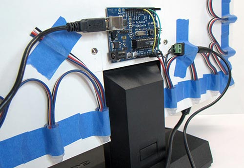
- Arduino controller, connectors and other little things.
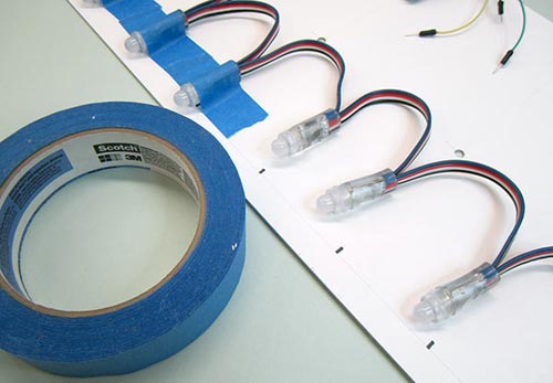
To facilitate connection to Arduino and PSU with tape, minor modifications were made. For the data and clock lines of the tape, connecting connectors were soldered so that they could be securely inserted into the Arduino connectors. To connect the power supply, a connector was soldered. A common ground was soldered from the connector to the Arduino. In the photo below, I think everything is quite clear:
In Arduino, the 13th pin was used for clock, and the 11th pin for data. Plus, don't forget the "ground".
Now, we need to decide how all this will be mounted on the back wall of the TV or monitor. There are many options here, and you can simply attach the LEDs with tape to the back of the monitor, or you can cut out a beautiful template or plexiglass. Our template would be made of thin plastic, with all the necessary cutouts for the monitor and mounts:
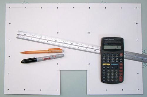
Then, you need to evenly space the 25 RGB LEDs. I got a distance between the LEDs of about 50mm.
When making the template, do not block the ventilation holes on the monitor, if any.
After all the RGB LED pixels are attached, all that remains is to attach the Arduino controller. Double-sided tape is best suited for these purposes. We connect the USB cable to the Arduino and the 5V power supply to the RGB LED strip.
Software
You can download all the necessary software from GitHub. In the Arduino->LEDstream folder there is a sketch for Arduino. Compile it and load it into the controller.
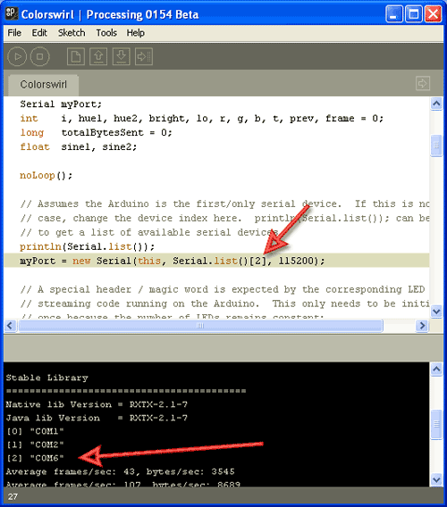
The computer uses software for the Processing IDE, which must be downloaded and installed separately (not to be confused with Arduino Processing!). If your configuration does not have 25 RGB LEDs, then changes will need to be made to the sketch. Also, you need to select the COM port to which the Arduino controller is connected to transfer data (see screenshot below).
The program works as follows: after launch, the program runs in the background and constantly takes screenshots of the screen and analyzes the colors of individual points around the perimeter. Then it calculates the average color for the points and transmits the data to the Arduino controller. And it doesn’t matter what is running on the computer - a media player, a browser with a YouTube video, or something else.
We will not consider the program code, because... it is well commented. By the way, in the Colorswirl folder there is a small example of a demo sketch that displays a rainbow on RGB LEDs.
Some old hardware may not be able to cope with the load (for example, the first Atoms on netbooks), because screenshots are constantly being taken. In this case, reducing the resolution, for example 800x600, can help.
Ambilight technology
The proprietary backlighting technology of the above-mentioned company consists of special lamps built into the TV that allow a soft glow to be projected in a certain way onto the wall behind the TV, which seems to continue the picture from the screen to increase immersion in the atmosphere of what is happening on the screen.
The technology itself was born in the last century due to the fact that, on the one hand, the brightness of the then TV receivers was insufficient, and viewers turned off the lights when watching them, on the other hand, watching TV in the dark put a sharp strain on the eyes, which led to rapid fatigue and general discomfort. The solution was obvious - the presence of a nearby source of diffused light (so-called TV lamps). Today, according to the Philips research department, this problem Ambilight technology is designed to solve this problem.
Currently, there are already 5 generations (and a lot of modifications) of this technology, of which the last three are the most common:
- Three-channel backlight technology " Ambilight Surround"with additional lamps on top of the body to expand the field of effects upward and independent binding of the left, right and upper block of background lamps to the corresponding area of the screen.
- Full backlight technology " Ambilight Full Surround", where the screen is already surrounded by lamps on all sides. Accordingly, the processor responsible for controlling the lamps builds the background image by analyzing at least four image zones on the screen. For best transmission light, the TV body is equipped with a rear screen panel.
- Technology " Ambilight Spectra”, which allows you to create a “volumetric” image thanks to more than 120 new generation LEDs and advanced image processing algorithms.
All technologies, to one degree or another, create diffuse light from behind the TV, which complements the colors and light intensity of the image displayed on the screen.
What can you say at the end of the review? The device is undoubtedly interesting and worth trying, especially considering that the manufacturer provides a free test drive for 30 days, i.e. if you don’t like the device, you can return it and get your money back. Your costs in this case will be equal to postage to the manufacturer. The main disadvantage is that the device only works in conjunction with software, which means you need a computer to get the effect. dynamic backlight.
Results
Well, the bottom line is:
pros
- work with any type of monitors and TV connected to a computer;
- low system requirements for PC hardware;
- fully implemented functionality that does not differ from that declared by the manufacturer;
- good software support, including from third-party software manufacturers;
- the ability to customize the product and create non-standard solutions;
- low price;
- wide possibilities for payment and delivery of goods;
- ease of installation and configuration;
- Russian-speaking technical support service;
- detailed text and video instructions on the manufacturer’s website;
- free test drive.
Minuses
- a computer is required to obtain the dynamic backlight effect;
- lack of software included in the package, the need to download it from the Internet;
- lack of instructions (even electronic) in the kit; the need to read it on the manufacturer’s website;
- lack of a number of fastening elements (double-sided tape) for LEDs;
- the need for a certain location of the screen (15-30 cm from the wall) to obtain the most correct effect;
- absence of a warranty card and manufacturer’s details both on the packaging and on the product itself.
A few years ago, mySKU had an amazing review posted by . The comments on this review are also amazing - it's just a huge knowledge base (so huge that the browser can barely load this page). Time passes, components become cheaper, mySKU finds a new audience that might have missed this review. I also decided to describe the process of creating adaptive backlighting for a TV or monitor like Philips Ambilight in my own words. Perhaps someone will find my review useful.
In 2007, Philips patented an incredibly simple, but, without exaggeration, amazing TV backlight technology. With such adaptive backlighting, the eyes become less tired when viewing in the dark, the presence effect increases, the display area expands, etc. Ambilight is applicable not only to video and photo content, but also to games. Ambilight has become business card Philips TVs. Since then, Philips has been closely vigilant so that none of the major manufacturers would even think of encroaching on the sacred by creating something similar. It is probably possible to license this technology, but the conditions are somehow prohibitive, and other market players are not particularly eager to do this. Small companies They also tried (and now there are companies that do this) to introduce similar technology in the form of separate kits, but punishment from Philips was inevitable. So, in the best case, if the company does not somehow renew the patent or its derivative, other manufacturers will only be able to produce something similar in 2027.
But such punishment does not apply to us, ordinary consumers. We are free to do what we see fit. Today I will tell you in detail how to make your own adaptive backlight for a TV or monitor like Philips Ambilight (hereinafter simply Ambilight). For some, the article will not contain anything new, because... There are dozens of such projects, and hundreds of articles have been written in different languages, and there are thousands of people who have already done this for themselves. But for many this can all be very interesting. You don't need any special skills. Only basic knowledge of physics for 8th grade high school. Well, just a little bit of soldering of wires.
So that you can better understand what I’m talking about, I’ll give you my example of what happened. The real costs for a 42" TV are about 1000 rubles and 2 hours of work.

The video does not convey all the sensations and effect in its entirety, but the children sat with their mouths open for the first time.
Possible implementation options
There are several options for implementing Ambilight. They depend on the video source.The cheapest, simplest and most effective option is a PC running Windows, Mac OS X or Linux as the signal source. Windows boxes on Atom processors, which cost from $70, are now very common. All of them are ideal for implementing Ambilight. I’ve been using various Windows boxes (in a TV stand) as a media player for several years now, I’ve written a small handful of reviews and consider them the best TV set-top boxes for media content. The hardware implementation of this option is the same for all of the above. operating systems. It is this option that I will talk about in the article.. The software part will relate to Windows system, AmbiBox will act as a universal control program. Can be used with Mac OS X and Linux.
The second option is that the signal source is a media set-top box based on Android, of which there are also a huge number. This option is the most problematic. First, the highlighting will only work in the Kodi media harvester (and its offshoots). Secondly, in the vast majority of cases, everything works only with hardware video decoding disabled, which is unacceptable for most boxes. The hardware implementation of the project also imposes certain requirements. I won’t touch on it, but if there’s something specific you’re interested in, I’ll try to answer in the comments.
The third option is a solution independent of the signal source. This is the most expensive, but absolutely universal solution, because... the signal is taken directly from the HDMI cable. For it you will need a fairly powerful microcomputer (such as a Raspberry Pi), an HDMI splitter, an HDMI-RCA AV converter, a USB 2.0 analog video capture device. Only with this option you can be guaranteed to use Ambilight with any TV set-top box/receiver, Android boxes, Apple TV, game consoles(for example, Xbox One, PlayStation 4) and other devices that have an HDMI output. For the version with 1080p60 support, the cost of components (without LED strip) will be about $70, with 2160p60 support - about $100. This option is very interesting, but a separate article needs to be written on it.
Hardware
To implement this, you will need three main components: a controlled LED RGB tape, power supply, Arduino microcomputer.First a little explanation.
WS2811 is a three-channel controller/driver (chip) for RGB LEDs with single-wire control (addressing an arbitrary LED). WS2812B is an RGB LED in an SMD 5050 package, which already has a WS2811 controller built into it.
For simplicity, the LED strips suitable for the project are called WS2811 or WS2812B.
WS2812B strip is a strip on which WS2812B LEDs are placed in series. The strip operates with a voltage of 5 V. There are strips with different densities of LEDs. Usually it is: 144, 90, 74, 60, 30 per meter. There are different degrees of protection. Most often these are: IP20-30 (protection against solid particles), IP65 (protection against dust and water jets), IP67 (protection against dust and protection against partial or short-term immersion in water to a depth of 1 m). Backing black and white.
Here is an example of such a tape:

WS2811 tape is a tape on which a WS2811 controller and some kind of RGB LED are placed in series. There are options designed for voltages of 5 V and 12 V. Density and protection are similar to the previous option.
Here is an example of such a tape:

There are also WS2811 “tapes” with large and powerful LEDs as in the photo below. They are also suitable for implementing Ambilight for some huge panel.

Which tape to choose, WS2812B and WS2811?
Important factor- power supply of the tape, which I will talk about a little later.
If you have a power supply at home that is suitable for power (often power supplies are left at home from old or damaged equipment), then choose a tape based on the voltage of the power supply, i.e. 5 V - WS2812B, 12 V - WS2811. In this case, you will simply save money.
From myself I can give a recommendation. If total There will be no more than 120 LEDs in the system, then WS2812B. If more than 120, then WS2811 with an operating voltage of 12 V. You will understand why this is so when it comes to connecting the tape to the power supply.
What level of tape protection should I choose?
For most, IP65 is suitable, because... On one side it is coated with “silicone” (epoxy resin), and on the other there is a 3M self-adhesive surface. This tape is convenient to mount on a TV or monitor and is convenient to wipe off dust.
What LED density should I choose?
For the project, strips with a density of 30 to 60 LEDs per meter are suitable (of course, 144 is possible, no one prohibits). The higher the density, the greater the Ambilight resolution (number of zones) and the greater the maximum overall brightness. But it’s worth considering that the more LEDs in the project, the more complex the strip’s power supply circuit will be, and more will be needed. powerful block nutrition. Maximum amount There are 300 LEDs in the project.
Buying tape
If your TV or monitor is hanging on the wall, and all 4 sides have a lot of free space nearby, then the tape is best placed at the back along the perimeter on all 4 sides for maximum effect. If your TV or monitor is installed on a stand, or there is little free space at the bottom, then the tape should be placed on the back on 3 sides (i.e. the bottom without tape).
For myself, I chose a white WS2812B IP65 strip with 30 LEDs per meter. I already had a suitable 5V power supply. I was deciding whether to use 60 or 30 LEDs per meter, but chose the latter after watching the video from ready-made examples implementation - the brightness and resolution suited me, and the power supply is easier to organize, there are fewer wires. Aliexpress has a huge number of lots of WS2812B tapes. I ordered 5 meters for $16. For my TV (42", 3 sides) I only needed 2 meters, i.e. I could buy it for $10, the remaining three meters for a friend. Prices often change among sellers, there are many offers, so just choose a cheap lot on Aliexpress with a high rating ( keywords for search - WS2812B IP65 or WS2811 12V IP65).


Buying a power supply for the tape
The power supply is selected according to power and voltage. For WS2812B - voltage 5 V. For WS2811 - 5 or 12 V. The maximum power consumption of one WS2812B LED is 0.3 W. For WS2811 in most cases it is the same. Those. The power supply power must be at least N * 0.3 W, where N is the number of LEDs in the project.
For example, you have a 42" TV, you chose a WS2812B strip with 30 LEDs per meter, you need 3 meters of strip on all 4 sides. You will need a power supply with a voltage of 5 V and a maximum power of 0.3 * 30 * 3 = 27 W , i.e. 5 V / 6 A. My implementation uses only 3 sides, a total of 60 LEDs (57 to be precise) - power from 18 W, i.e. 5 V / 4 A.
I’ve had the ORICO CSA-5U (8 A) multiport USB charger lying idle for a long time, left over from an old review. Its ports are powered in parallel (this is critically important), this charger is ideal for me as a power supply, because... I will connect the tape through 2 parallel connections (explanations will be later in the article).

If I didn’t have this charger, I would have chosen it (but in the comments they write that they often put 2.5 A inside, so it’s better to study this issue in more detail).

Buying a microcomputer
Ambilight will be controlled by an Arduino microcomputer. Arduino Nano On Aliexpress it costs about a piece.

Costs for my option (for 42" TV):
$10 - 2 meters WS2812B IP65 (30 LEDs per meter)
$4 - 5 V / 4 A power supply (I didn’t spend any money on a power supply, I’m giving the cost for clarity)
$2.5 - Arduino Nano
-----------
16,5$
or 1000 rubles
Hardware implementation
The most important thing is to properly organize the power supply for the tape. The tape is long, the voltage sags at high currents, especially at 5 V. Most of the problems that arise for those who make their own Ambilight are related to power supply. I use the rule - you need to make a separate power supply for every 10 W of maximum power consumption at 5 V and 25 W of power consumption at 12 V. The length of the power supply (from the power supply to the tape itself) should be minimal (without reserve), especially at 5 IN.
The general connection diagram is as follows (the diagram shows the power connection for my version):

Power is supplied to the tape at both ends - two parallel connections. For example, if I were lighting on all 4 sides, and the strip had 60 LEDs per meter (i.e. maximum power 54 W), then I would make the following power supply:

The connecting wires must be used appropriately; the smaller the gauge (AWG), the better, so that they are sufficient for the calculated current strength.
Two contacts go to the Arduino from the tape. GND, which needs to be connected to the corresponding pin on the Arduino. And DATA, which needs to be connected to the sixth digital pin through a 300-550 Ohm resistor (preferably 470 Ohms). If you don’t have a resistor, then in most cases everything will work fine without it, but it’s better to have one. You can buy a resistor for a couple of kopecks at any radio store. The Arduino microcomputer itself can be placed in any convenient case; many people use a Kinder surprise egg for this. The Arduino should be placed as close to the tape as possible so that the DATA connection has a minimum length.
Soldering wires to the tape is simple. The main rule is that the contact time with the soldering iron should be minimal; you cannot “mess around” with the soldering iron.
In my case it turned out like this:


Two black high-quality USB cables were used for power, and a white one for connecting to the computer. I ran out of white heat shrink tubing so I used red ones. Not as “pretty”, but it suits me (it’s hidden behind the TV anyway).
Important question- how to bend the tape at right angles? If you have a strip of 60 LEDs, then the strip needs to be cut and connected with short wires (placing it all in a heat-shrinkable tube). You can buy special three-pin corner connectors for LED strips (there are 4 pins in the picture, just for example):

If you have a strip of 30 LEDs, then the distance between the LEDs is large, you can easily make a corner without cutting. Remove a piece of the “silicone” coating, insulate (you can even use tape) the contact pad and bend it according to the diagram:
I cut a piece of tape to practice. The main thing is not to overdo it - bend it slightly once and that’s it. There is no need to bend it here and there, there is no need to press the bend line too hard.

Here is a view from the back of the TV, all the wires go through the hole into the cabinet:

Software part
This is the simplest thing.We connect the Arduino microcomputer via USB. Driver ( serial interface CH340) will be installed automatically. If this does not happen, then in the Arduino IDE folder there is a Drivers folder with everything you need.
Launch the Arduino IDE and open the Adalight.ino file.

We change the number of LEDs in the code. I'm 57.

Tools > Board > Arduino nano
Tools > Port > Select the COM port (the desired option will be there)
Click the “Download” button:

The program will inform you when the download is complete (this is literally a couple of seconds).
Ready. You need to disconnect the Arduino from USB and connect it again. The tape will light up sequentially in red, green and blue - the Arduino has been activated and is ready for use.
Download and install the program. In the program, click “More settings” and specify the device - Adalight, COM port and the number of LEDs. Select the number of frames to capture (up to 60).

Next, click “Show Capture Zones” > “Zone Setup Wizard”. Select your ribbon configuration.

Click Apply and Save Settings. On this basic settings are ending. Then you can experiment with the size of the capture zones, color correct the tape, etc. The program has many different settings.

To activate a profile, just double-click on the corresponding icon (AmbiBox profiles) in the Windows notification area. The tape will light up immediately. It can also be turned off by double clicking.
That's basically it. You saw the result at the beginning of the article. Nothing complicated, cheap and healthy. I'm sure you can do better!
In 2007, Philips patented an incredibly simple, but, without exaggeration, amazing TV backlight technology. With such adaptive backlighting, the eyes become less tired when viewing in the dark, the presence effect increases, the display area expands, etc. Ambilight is applicable not only to video and photo content, but also to games. Ambilight has become a hallmark of Philips TVs. Since then, Philips has been closely vigilant so that none of the major manufacturers would even think of encroaching on the sacred by creating something similar. It is probably possible to license this technology, but the conditions are somehow prohibitive, and other market players are not particularly eager to do this. Small companies also tried (and there are now companies that are doing this) to introduce similar technology in the form of separate kits, but punishment from Philips was inevitable. So, in the best case, if the company does not somehow renew the patent or its derivative, other manufacturers will only be able to produce something similar in 2027.
But such punishment does not apply to us, ordinary consumers. We are free to do what we see fit. Today I will tell you in detail how to make your own adaptive backlight for a TV or monitor like Philips Ambilight (hereinafter simply Ambilight). For some, the article will not contain anything new, because... There are dozens of such projects, and hundreds of articles have been written in different languages, and there are thousands of people who have already done this for themselves. But for many this can all be very interesting. You don't need any special skills. Only basic knowledge of physics for the 8th grade of high school. Well, just a little bit of soldering of wires.
So that you can better understand what I’m talking about, I’ll give you my example of what happened. The real costs for a 42" TV are about 1000 rubles and 2 hours of work.
The video does not convey all the sensations and effect in its entirety, but the children sat with their mouths open for the first time.
Possible implementation options
There are several options for implementing Ambilight. They depend on the video source.The cheapest, simplest and most effective option is a PC running Windows, Mac OS X or Linux as the signal source. Windows boxes on Atom processors, which cost from $70, are now very common. All of them are ideal for implementing Ambilight. I’ve been using various Windows boxes (in a TV stand) as a media player for several years now, I’ve written a small handful of reviews and consider them the best TV set-top boxes for media content. The hardware implementation of this option is the same for all of the listed operating systems. It is this option that I will talk about in the article.. The software part will be related to the Windows system; AmbiBox will act as a universal control program. Can be used with Mac OS X and Linux.
The second option is that the signal source is a media set-top box based on Android, of which there are also a huge number. This option is the most problematic. First, the highlighting will only work in the Kodi media harvester (and its offshoots). Secondly, in the vast majority of cases, everything works only with hardware video decoding disabled, which is unacceptable for most boxes. The hardware implementation of the project also imposes certain requirements. I won’t touch on it, but if there’s something specific you’re interested in, I’ll try to answer in the comments.
The third option is a solution independent of the signal source. This is the most expensive, but absolutely universal solution, because... the signal is taken directly from the HDMI cable. For it you will need a fairly powerful microcomputer (such as a Raspberry Pi), an HDMI splitter, an HDMI-RCA AV converter, a USB 2.0 analog video capture device. Only with this option you can be guaranteed to use Ambilight with any TV set-top box/receiver, Android boxes, Apple TV, game consoles (for example, Xbox One, PlayStation 4) and other devices that have an HDMI output. For the version with 1080p60 support, the cost of components (without LED strip) will be about $70, with 2160p60 support - about $100. This option is very interesting, but a separate article needs to be written on it.
Hardware
To implement it, you will need three main components: a controllable RGB LED strip, a power supply, and an Arduino microcomputer.First a little explanation.
WS2811 is a three-channel controller/driver (chip) for RGB LEDs with single-wire control (addressing an arbitrary LED). WS2812B is an RGB LED in an SMD 5050 package, which already has a WS2811 controller built into it.
For simplicity, the LED strips suitable for the project are called WS2811 or WS2812B.
WS2812B strip is a strip on which WS2812B LEDs are placed in series. The strip operates with a voltage of 5 V. There are strips with different densities of LEDs. Usually it is: 144, 90, 74, 60, 30 per meter. There are different degrees of protection. Most often these are: IP20-30 (protection against solid particles), IP65 (protection against dust and water jets), IP67 (protection against dust and protection against partial or short-term immersion in water to a depth of 1 m). Backing in black and white.
Here is an example of such a tape:

WS2811 tape is a tape on which a WS2811 controller and some kind of RGB LED are placed in series. There are options designed for voltages of 5 V and 12 V. Density and protection are similar to the previous option.
Here is an example of such a tape:

There are also WS2811 “strips” with large and powerful LEDs, as in the photo below. They are also suitable for implementing Ambilight for some huge panel.

Which tape to choose, WS2812B and WS2811?
An important factor is the power supply of the tape, which I will talk about a little later.
If you have a power supply at home that is suitable for power (often power supplies are left at home from old or damaged equipment), then choose a tape based on the voltage of the power supply, i.e. 5 V - WS2812B, 12 V - WS2811. In this case, you will simply save money.
From myself I can give a recommendation. If the total number of LEDs in the system is no more than 120, then WS2812B. If more than 120, then WS2811 with an operating voltage of 12 V. You will understand why this is so when it comes to connecting the tape to the power supply.
What level of tape protection should I choose?
For most, IP65 is suitable, because... On one side it is coated with “silicone” (epoxy resin), and on the other there is a 3M self-adhesive surface. This tape is convenient to mount on a TV or monitor and is convenient to wipe off dust.
What LED density should I choose?
For the project, strips with a density of 30 to 60 LEDs per meter are suitable (of course, 144 is possible, no one prohibits). The higher the density, the greater the Ambilight resolution (number of zones) and the greater the maximum overall brightness. But it’s worth considering that the more LEDs in the project, the more complex the strip’s power supply circuit will be, and a more powerful power supply will be needed. The maximum number of LEDs in a project is 300.
Buying tape
If your TV or monitor is hanging on the wall, and all 4 sides have a lot of free space nearby, then the tape is best placed at the back along the perimeter on all 4 sides for maximum effect. If your TV or monitor is installed on a stand, or there is little free space at the bottom, then the tape should be placed on the back on 3 sides (i.e. the bottom without tape).
For myself, I chose a white WS2812B IP65 strip with 30 LEDs per meter. I already had a suitable 5V power supply. I was deciding whether to use 60 or 30 LEDs per meter, but chose the latter after reviewing the video with ready-made examples of implementation - the brightness and resolution suited me, and the power supply was easier to organize and there were fewer wires. Aliexpress has a huge number of lots of WS2812B tapes. I ordered 5 meters for $16. For my TV (42", 3 sides) I only needed 2 meters, i.e. I could buy it for $10, the remaining three meters for a friend. Prices often change among sellers, there are many offers, so just choose a cheap lot on Aliexpress with a high rating (search keywords - WS2812B IP65 go WS2811 12V IP65).


Buying a power supply for the tape
The power supply is selected according to power and voltage. For WS2812B - voltage 5 V. For WS2811 - 5 or 12 V. The maximum power consumption of one WS2812B LED is 0.3 W. For WS2811 in most cases it is the same. Those. The power supply power must be at least N * 0.3 W, where N is the number of LEDs in the project.
For example, you have a 42" TV, you chose a WS2812B strip with 30 LEDs per meter, you need 3 meters of strip on all 4 sides. You will need a power supply with a voltage of 5 V and a maximum power of 0.3 * 30 * 3 = 27 W , i.e. 5 V / 6 A. My implementation uses only 3 sides, a total of 60 LEDs (57 to be precise) - power from 18 W, i.e. 5 V / 4 A.
I’ve had the ORICO CSA-5U (8 A) multiport USB charger lying idle for a long time, left over from an old review. Its ports are powered in parallel (this is critically important), this charger is ideal for me as a power supply, because... I will connect the tape through 2 parallel connections (explanations will be later in the article).

If I didn’t have this charger, I would have chosen it (there is information that this particular power supply is equipped with 2.5 A internals, so you need to study this issue in more detail with the seller, or look at other models).

Buying a microcomputer
Ambilight will be controlled by an Arduino microcomputer. Arduino Nano on Aliexpress costs about apiece.

Costs for my option (for 42" TV):
$10 - 2 meters WS2812B IP65 (30 LEDs per meter)
$4 - 5 V / 4 A power supply (I didn’t spend any money on a power supply, I’m giving the cost for clarity)
$2.5 - Arduino Nano
-----------
16,5$
or 1000 rubles
Hardware implementation
The most important thing is to properly organize the power supply for the tape. The tape is long, the voltage sags at high currents, especially at 5 V. Most of the problems that arise for those who make their own Ambilight are related to power supply. I use the rule - you need to make a separate power supply for every 10 W of maximum power consumption at 5 V and 25 W of power consumption at 12 V. The length of the power supply (from the power supply to the tape itself) should be minimal (without reserve), especially at 5 IN.
The general connection diagram is as follows (the diagram shows the power connection for my version):

Power is supplied to the tape at both ends - two parallel connections. For example, if I were lighting on all 4 sides, and the strip had 60 LEDs per meter (i.e. maximum power 54 W), then I would make the following power supply:

The connecting wires must be used appropriately; the smaller the gauge (AWG), the better, so that they are sufficient for the calculated current strength.
Two contacts go to the Arduino from the tape. GND, which needs to be connected to the corresponding pin on the Arduino. And DATA, which needs to be connected to the sixth digital pin through a 300-550 Ohm resistor (preferably 470 Ohms). If you don’t have a resistor, then in most cases everything will work fine without it, but it’s better to have one. You can buy a resistor for a couple of kopecks at any radio store. The Arduino microcomputer itself can be placed in any convenient case; many people use a Kinder surprise egg for this. The Arduino should be placed as close to the tape as possible so that the DATA connection has a minimum length.
Soldering wires to the tape is simple. The main rule is that the contact time with the soldering iron should be minimal; you cannot “mess around” with the soldering iron.
In my case it turned out like this:


Two black high-quality USB cables were used for power, and a white one for connecting to the computer. I ran out of white heat shrink tubing so I used red ones. Not as “pretty”, but it suits me (it’s hidden behind the TV anyway).
An important question is how to bend the tape at a right angle? If you have a strip of 60 LEDs, then the strip needs to be cut and connected with short wires (placing it all in a heat-shrinkable tube). You can buy special three-pin corner connectors for LED strips (there are 4 pins in the picture, just for example):

If you have a strip of 30 LEDs, then the distance between the LEDs is large, you can easily make a corner without cutting. Remove a piece of the “silicone” coating, insulate (you can even use tape) the contact pad and bend it according to the diagram:
I cut a piece of tape to practice. The main thing is not to overdo it - bend it slightly once and that’s it. There is no need to bend it here and there, there is no need to press the bend line too hard.

Here is a view from the back of the TV, all the wires go through the hole into the cabinet:

Software part
This is the simplest thing.We connect the Arduino microcomputer via USB. The driver (CH340 serial interface) will be installed automatically. If this does not happen, then in the Arduino IDE folder there is a Drivers folder with everything you need.
Launch the Arduino IDE and open the Adalight.ino file.

We change the number of LEDs in the code. I'm 57.

Tools > Board > Arduino nano
Tools > Port > Select the COM port (the desired option will be there)
Click the “Download” button:

The program will inform you when the download is complete (this is literally a couple of seconds).
Ready. You need to disconnect the Arduino from USB and connect it again. The tape will light up sequentially in red, green and blue - the Arduino has been activated and is ready for use.
Download and install the program. In the program, click “More settings” and specify the device - Adalight, COM port and the number of LEDs. Select the number of frames to capture (up to 60).

Next, click “Show Capture Zones” > “Zone Setup Wizard”. Select your ribbon configuration.

Click Apply and Save Settings. This completes the basic settings. Then you can experiment with the size of the capture zones, color correct the tape, etc. The program has many different settings.

To activate a profile, just double-click on the corresponding icon (AmbiBox profiles) in the Windows notification area. The tape will light up immediately. It can also be turned off by double clicking.
That's basically it. You saw the result at the beginning of the article. Nothing complicated, cheap and healthy. I'm sure you can do better, so share your crafts in the comments.

