29.06.2020
Connecting the IR receiver to the arduino nano. Arduino Uno. Connecting the IR receiver. Description of the main functions of the library
IR receiver and infrared remote control remote control- the most common and simplest way to control electronic equipment. The infrared radiation spectrum is not visible to the human eye, but it is perfectly received by IR receivers that are built into electronic devices. Arduino ir remote modules are used to control various equipment in line of sight.
The widespread use of IR emitters has become possible due to their low cost, simplicity and ease of use. IR radiation lies in the range from 750 to 1000 microns - this is the closest part of the spectrum to visible light. In the region of infrared radiation, the optical properties of various materials can change. Some glasses, for example, become opaque to IR rays, while paraffin, on the contrary, is transparent in the IR spectrum.
Radiation is recorded using special photographic materials, on the basis of which receivers are made. In addition to heated bodies (the Sun, incandescent lamps or candles), the source of infrared radiation can be solid-state devices - IR LEDs, lasers. Radiation in infrared range has a number of features that make them convenient to use in remote controls:
- Solid state emitters (IR LEDs) are cheap and compact.
- Infrared rays are not perceived or detected by the human eye.
- IR receivers are also cheap and small in size.
- Low interference since the transmitter and receiver are tuned to the same frequency.
- Absent Negative influence on human health.
- High reflectance from most materials.
- IR emitters do not affect the operation of other devices.
 The remote control works as follows. When you press the button, the signal is encoded in infrared light, the receiver receives it and performs the required action. Information is encoded as a logical sequence of pulse packets with a certain frequency. The receiver receives this sequence and demodulates the data. To receive the signal, a microcircuit is used, which contains a photodetector (photodiode), amplifiers, band pass filter, a demodulator (a detector that allows you to isolate the signal envelope) and an output transistor. It also has filters – electrical and optical. Such devices operate at a distance of up to 40 meters. The IR method of data transmission exists in many devices: in household appliances, industrial equipment, computers, fiber optic lines.
IR receiver Arduino
To read the IR signal you will need the Arduino board itself, a breadboard, an IR signal receiver and jumpers. There are a huge variety of different receivers, but it is better to use TSOP312 or others suitable for Arduino. Data from the remote control to the receiver can be transmitted via the RC5 or NEC protocol.
To determine which leg belongs to what, you need to look at the sensor from the receiver side. Then on the receiver the central contact is ground, on the left is the output to the microcontroller, on the right is power.


For convenience, you can use ready-made IR receiver modules.


Connecting the IR receiver to Arduino
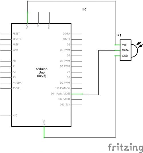
The IR receiver outputs are connected to the Arduino to the GND, 5V and digital input ports. The diagram for connecting the sensor to the 11th digital pin is shown below.
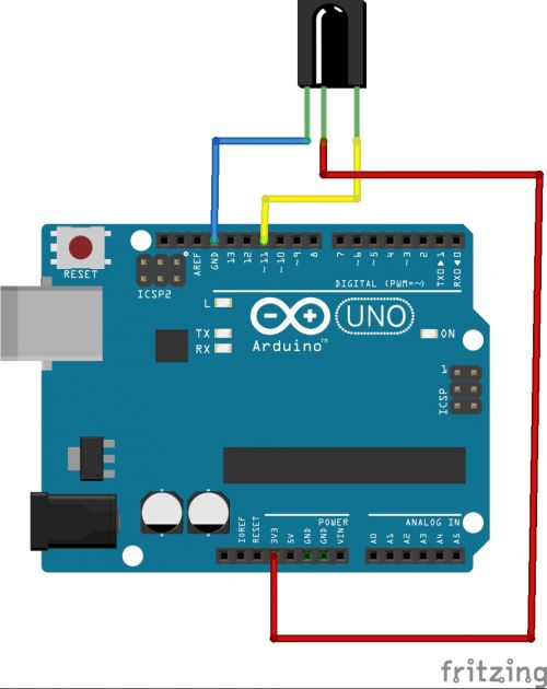
This is what the circuit with the infrared receiver module looks like:

Libraries for working with IR
To work with IR devices, you can use the IRremote library, which simplifies the construction of control systems. You can download the library. After downloading, copy the files to the \arduino\libraries folder. To connect to your library sketch, you need to add the header file #include
To read information, use the IRrecvDumpV2 example from the library. If the remote control already exists in the list of recognized ones, then scanning is not required. To read the codes, you need to launch the ARduino IDE and open the IRrecvDemo example from IRremote.
There is a second library for working with IR signals - this is IRLib. It is similar in functionality to the previous one. Compared to IRremote, IRLib has an example for determining the frequency of an IR sensor. But the first library is simpler and more convenient to use.
After loading the library, you can start reading the received signals. The following code is used for this.
The decode_results operator is needed to assign the variable name results to the received signal.
In the code you need to rewrite "HEX" to "DEC".
Then, after loading the program, you need to open the serial monitor and press the buttons on the remote control. Various codes will appear on the screen. You need to make a note indicating which button the received code corresponds to. It is more convenient to record the obtained data in a table. This code can then be written into the program so that the device can be controlled. The codes are written into the memory of the Arduino EEPROM board itself, which is very convenient, since you don’t have to program the buttons every time you turn on the remote control.
It happens that when loading a program, the error “TDK2 was not declared In his scope” is displayed. To fix it, you need to go to Explorer, go to the folder in which the Arduino IDE application is installed and delete the files IRremoteTools.cpp and IRremoteTools.h. After this, you need to reload the program onto the microcontroller.
Conclusion
Using Arduino ir remote makes life easier for the user. Can act as a remote control mobile phone, tablet or computer - you just need special software for this. Using Arduino you can centralize all control. With one button on the remote control you can perform several actions at once - for example, turn on the TV and Blu-Ray at the same time.
Today's article will look at connecting the TSOP34836 IR receiver to the Aduino UNO board. For these purposes, you can use any receiver you have that is frequency compatible with your remote control. The assignment of the pins is shown in the figure.
1. Vout – receiver output.
2. GND – “ground”, common wire.
3. Vcc – power supply.
Data transfer from the IR remote control to the receiver is carried out using the RC5 protocol, which is a sequence of pulses. The connection is made according to the following diagram.
And having collected, we get something like this:
To process the data transmitted by the remote control, we use the IRremote library, this library is attached to the article. Paste the following code:
#include "IRremote.h" IRrecv irrecv(11); // Specify the pin to which the receiver is connected decode_results results; void setup() ( Serial.begin(9600); // Set the speed of the COM port irrecv.enableIRIn(); // Start receiving ) void loop() ( if (irrecv.decode(&results)) // If data arrived ( Serial .println(results.value, HEX); // Send the received data to the console irrecv.resume(); // Accept the next command ) )
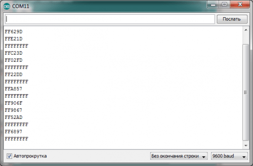
Now in the COM port console you can see the code of the pressed key in HEX.
That's all, now you can use this circuit in your devices. Below is an example of one practical applications IR receiver.
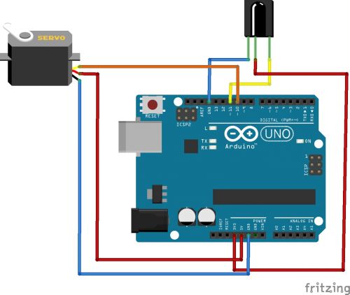
As a demonstration, it will be shown how to control a servo using an IR remote control.
Device diagram:

This is what it should look like:
To operate the device we use the following code:
#include "Servo.h" #include "IRremote.h" IRrecv irrecv(11); decode_results results; Servo servoMain; int servPoz = 90; //Initial position of the servo int lastPoz = 0; void setup() ( irrecv.enableIRIn(); servoMain.attach(10); // Servo is attached to pin 10 servoMain.write(servPoz); ) void loop() ( if (irrecv.decode(&results)) ( int res = results.value; Serial.println(res, HEX); if(res==0xFFFF906F) // If the "+" button is pressed ( lastPoz=res; servPoz++; servoMain.write(servPoz); ) else if(res== 0xFFFFA857) // If the "-" button is pressed ( servPoz--; lastPoz=res; servoMain.write(servPoz); ) else if(res==0xFFFFFFFF) // If the button is held ( if(lastPoz==0xFFFF906F) servPoz++; // Hold "+" if(lastPoz==0xFFFFA857) servPoz--;// Hold "-" servoMain.write(servPoz); ) irrecv.resume(); delay(100); ) )
The remote control used is some kind of Chinese, when you press “+” the servo rotates in one direction, when you press “-” it rotates in the other.
Every home has a TV remote control, or another remote control. This device allows you to control any device from a distance, which is very convenient. There is no need to waste precious calories and make unnecessary movements. If you have any device and you would like to control it from a distance, then you can remote control this device. If you wish, you can make a remote control with your own hands, but there is no need for this and that’s another story. Why might you need remote control?! - it's simple:
Laziness is a quality that forces us to make great efforts to reduce overall energy costs.
For the first time, remote control in action was shown to the world by inventor Nikola Tesla; in 1898, at an exhibition in Madison Square Garden, he presented a radio-controlled boat called “teleautomatic”. Today, this technology has become widespread, only more different ways transmission of commands (communication channel).
The main communication channels include:
- Radio channel
- Ultrasonic
- Infrared
In this article we will talk about controlling the device with an infrared remote control. Infrared radiation - electromagnetic radiation, occupying the spectral region between the red end of visible light and microwave radiation. Infrared radiation is not visible to the human eye, but can be seen with a camera or video camera. This is often how they check the functionality of the TV remote control at home.
How long ago old job I took the remote control and the “peephole” (IR receiver) from the security system that was being written off, it lay idle for a long time and finally I got around to checking it in operation.

Having disassembled this receiver, I saw some trick; in this “eye” 4 IR receivers were soldered together. This was done in order to receive IR waves from four sides. And it’s convenient, you don’t need to limit yourself to a certain reception angle.

I also sketched out a similar circuit with four receivers, in case I need it. I used TSOP1836 IR receivers, but you can use others. To ensure 360-degree reception, you need to select appropriate IR receivers (with a wide reception angle) and place them as close as possible to each other. I didn't notice any reception problems with my receivers. I also added it to the attachment printed circuit board and arrangement of elements.

To process commands I will naturally use arduino uno; I can use an IR receiver
TSOP34836 (has a high reception range, but is more expensive) or TL1838. You can take any IR remote control, even from a TV. Well, if you need your own remote control, you can buy a kit for arduino.
Principle of operation:
When you press a button on the remote control, it sends the button code in infrared light, after which the receiver receives this button code and sends it to the actuator, which, depending on the button, will perform a certain action.
You can also transmit information over a short distance using IR waves. To transmit your commands or information, you can use a second arduino with an IR transmitter. But the speed of such transmission is very slow. The advantages of the infrared channel include insensitivity to electromagnetic interference.
To receive arduino IR signals, we will connect the IR receiver as follows:

Please note that the location of the receiver legs may vary.


![]()
The receiver has 3 legs, “+” and “-” power supply (mainly voltage 3.3-5V) and the data leg is what transmits information to the device (in our case, arduino). The supply voltage for TSOP34836 is 2.7-5.5 volts. I will use 5 volts from the standard arduino output.
Well, of course you need firmware for arduino. The operating algorithm will be as follows: when you press the top button of the remote control, the arduino turns on the relay, and when you press it again, it turns it off. Using this relay, you can power, for example, the backlight, but it is not necessary to program a button press on the relay; you can output a command to the computer or perform a certain operation in arduino, etc.
To simplify the work, we will use a ready-made library. Firmware code:
#include
void setup() (
Serial.begin(9600);
irrecv.enableIRIn(); // turn on the receiver
pinMode(RELAY_PIN, OUTPUT); // configure the relay for output
digitalWrite(RELAY_PIN,HIGH); //set the value high
}
void loop() (
if (irrecv.decode(&results)) (//if data is received
Serial.print("0x");
Serial.println(results.value, HEX);//output the received message to the terminal
if ((results.value == 0x8FF40BF) ||(results.value == 0xD72040BF)) digitalWrite(RELAY_PIN, !digitalRead(RELAY_PIN));//if the button code is 0x8FF40BF or 0xD72040BF change the relay state to the opposite
delay(200); // delay from double triggering
irrecv.resume();// Get the next value
}
}
Let me explain a little with the sketch:
if ((results.value == 0x8FF40BF) ||(results.value == 0xD72040BF))
The resulting value is compared with "0x8FF40BF" and "0xD72040BF" - these are button codes in hexadecimal notation. Two meanings only because I use two remote controls with unique codes.
digitalWrite(RELAY_PIN, !digitalRead(RELAY_PIN));
Standard procedure for digital pin recording except for "!digitalRead(RELAY_PIN)". Sign "!" denotes inversion, in our case the inversion of the state of the digital output "RELAY_PIN".
Serial.print("0x");
Serial.println(results.value, HEX);//output the received message to the terminal
These lines output all received codes to the terminal. IN work program this is unnecessary, but you need to find out required code one button or another. That is, first we upload the sketch to the Arduino, go to the terminal and by clicking on the button we will get the desired code.
Also in the IRremote library there are several different examples, which may be useful.
In the attachment to the article:
- sketch for arduino
- PCB for 4 sensors
The IR Receiver module in combination with an IR remote control will allow you to easily implement remote control of the Arduino board.
It is nothing more than a VS1838B IR receiver with the manufacturer’s recommended harness installed on the board.
To work with this module out of the box, you need a remote control with a frequency of 38 kHz.
The advantage of this board is the push-in connector, which allows you to replace the IR receiver with another one operating at the frequency required for your project without soldering.
Main technical characteristics:
Supply voltage: 2.7 - 5.5V
Modulation frequency: 38kHz
Temperature range: - 20 ... + 80°C
Interface: Digital
Connecting to Arduino
The module is equipped with a three-pin 2.54mm connector
: connects to GND pin
: connects to +5V output
: connects to digital pin (D2 in example)

An example of working in the Arduino environment
To work with this module you need to install the IRRemote library
Download, unpack and put it in the libraries folder in the Arduino folder. If the Arduino IDE was open at the time of adding the library, reboot the environment.
Reading remote control buttons
To read the remote control readings, fill in the sketch below. It will output the encoding of the pressed buttons to the port.
As an example, we will use the remote control, as in the picture, because This type of remote control is included in the set
You can read about the differences in the operating logic of various remote controls in the original article from a member of our community under the nickname

Sample code:
#includeYou should see the following in the port monitor:
By holding each button for almost a second, we get about 10 codes. The first one is the button code. And after it, a standard code begins to appear, which reports that the button is stuck.
Controlling Arduino board with remote control
Let's make the LED on the Arduino board (D13) light up when the first button is encoded and turn off when the second button is encoded.
Sample code:
// Tested on Arduino IDE 1.0.3#includeRecently I needed to control the TV remote control small project on arduino. The idea was to control the air conditioner through the arduino with temperature sensor. My air conditioner comes with a fairly convenient remote control, but we need to automate turning it on, setting the temperature and turning it off. As a result of a long search, I was able to find a solution for myself. More details about it under the cut.
How it works
Connecting IR receiver, we direct remote control to the receiver, record the signal and output it to Serial. (since this is the first part of the article, we do not consider sending a signal. We will talk about sending in the second part).
What do we need
- Arduino(or analogues, I use Tosduino- 2 times cheaper, fully compatible with regular arduino)
- Light-emitting diode ( LED)
- 220 kOhm resistor
- IR receiver from the series
Connection
IR Receiver
LED
| Arduino | Breadboard | Arduino |
|---|---|---|
| pin number 11 | resistor 220 kOhm | GND (GrouND) |

IR technology
The cheapest way to remotely control a device within visible reach using infrared radiation. Almost all audio and video equipment can be controlled in this way. Thanks to its widespread availability, the required components are quite cheap, making this technology ideal for us who like to use IR remote control for our own projects.
Infrared radiation is actually normal light with a specific color. We humans cannot see this color because its wavelength is 950 nm, which is below the visible spectrum. This is one of the reasons why IR is chosen for telemechanics needs, we want to use it, but we are not interested in seeing it. Though we can't see infrared light, emitted from the remote control, but that doesn't mean we can't make it visible.
Video camera or digital camera“sees” infrared light, as you can see in the video below. Even the cheapest ones Cell Phones have built-in cameras. Just point the remote control at such a camera, press any button, and you will see the LED flickering.
A series of miniature receivers for infrared remote control systems. The PIN diode and preamplifier are assembled on a lead frame, and are designed as IR filter. The demodulated output signal can be directly decoded by the microprocessor. - This is a standard receiver, supports all major transmission codes.

| Part | Carrier Frequency |
|---|---|
| 30 kHZ | |
| 33 kHZ | |
| 36 kHZ | |
| 36.7 kHZ | |
| 38 kHZ | |
| 40 kHZ | |
| 56 kHZ |
IRremote.h
Download library IRremote you can from my repository on Github.com
To install this library, copy the contents of the archive to: arduino-1.x/libraries/IRremote Where arduino-1.x is the folder where the Arduino IDE is installed. Then the file arduino-1.x/libraries/IRremote/IRremote.cpp should be available and IRremote.h
Example No. 1 - we get the code for the remote control button
This sketch will read the code of the button pressed on the remote control and send information about this button to the Serial port so that we can then use this code.
#include
I will use these button codes in all of the following examples:

Example No. 2 - assigning a name to the remote control button
Let's send the names of the buttons to the Serial port. (first we must catch the codes of these buttons and assign names to them, look at the code, I think everything will be clear there).
#include
Example No. 3 - turn on the LED using the remote control button
Now let's teach our Arduino turn on the LED on PIN 11 via a button on the remote control
#include
Example No. 4 - PWM with remote control
Now let's control the brightness of our LED (since it is connected to port 11, which has PWM, there should be no problems). The up and down buttons on the remote control will be used to control the brightness.
#include
Somehow like this. The second part of the article will discuss how we can send the received signal to our equipment. In my case it was the air conditioner. Also in the second part there will be a video that will show the turnkey assembly, from start to finish + an example of work.

