29.06.2020
Charger circuits magazine model designer. Welding machine with pulsating current. For the "emotion meter" circuit
Central Committee Communist Party Soviet Union pays great attention to automation and mechanization of agriculture and industry.
Many farms now have their own computer centers and control centers that allow the best way work off technological process, uninterrupted dispatch communication with any part of the enterprise. A major role in dispatch communications at this time is played by such means of communication as automatic telephone communication (ATS), dispatch switches, intercoms, and television.
All these types of communications are currently available only at large industrial enterprises and agricultural complexes. For low-power enterprises, where it is impractical to install automatic telephone exchanges and high-capacity switches, the young innovators of the Bashkir RSUT made a proposal to make switch for 10 numbers.
As a basis for their design, the circle members took the description of the switch published in the magazine "Modelist-Constructor" No. 6 for 1974. Having made a number of design changes, the circle members created the "Signal-4" and "Signal-5" switches, which are more convenient to use and have better appearance than the switch described in the "Modeler-Constructor" magazine.
The circuit of this switch is extremely simple and, naturally, much cheaper and lighter than the KOS-22 switch produced by our industry, which in many cases is not used at full capacity due to the fact that a low-power enterprise does not need such a number of subscribers.
There is not much work to do on such a switch. The call rings and the subscriber number light comes on. The dispatcher turns on the key, under which the light is on, and hears the subscriber.
The subscriber calls the switchboard by lifting the handset from the device. At the same time, the “Call” light on the switch and the light of the given subscriber light up and the call rings. The bell can be turned off, in which case the dispatcher will know that he is being called by the lights that come on.
To call a subscriber, 110 V alternating current is supplied to the line. The “Signal-4” and “Signal-5” switches are powered from the AC mains and consume 15 W of power.
The switch operates as follows: when the subscriber picks up the handset, the circuit is closed through contacts 2-3 and 5-4, the relay is activated and its contacts turn on the bell and the corresponding light bulb of the subscriber. The sending voltage passes from the transformer through contacts 5-6 and 2-3 to the call of the subscriber's telephone set. When you make a call, the "Ranging Call" light on the switch lights up.
The switch uses parts common in telephony, i.e. keys with a one-way lock. The Signal-5 switch uses two 5-key switches (you can use one 10-key switch with two groups of switching contact groups). Small-sized relays such as RES-22, RES-6, 12 V signal switch lamps (you can also use ordinary 6.3 and 13.5 V lamps).
The transformer can be taken from the Record receiver and the like with rewinding the secondary windings at 28 and 110 V. If it is necessary to increase the capacity, the switches can be paired and even stacked. The "Signal-5" switch is made in the case of a calendar-informant, "Signal-4" - in homemade building made of plywood, finished with textured plastic.
In 1977, the All-Russian meeting of young friends of nature took place in Ufa. At this meeting for the first time the section " Young technicians- forestry." The program of the section included speeches by schoolchildren about their work experience, defense of projects best designs, an exhibition of models and working samples of homemade equipment used in forestry.
As one of the participants in the rally, V. Nosaev, a student of school No. 81 in Chelyabinsk, said in his speech, in the House of Young Technicians of the Chelyabinsk Tractor Plant named after V.I. Lenin, which has existed for 20 years, various clubs operate: auto-tractor, mechanical engineering, design , radio, telemechanics, electronics, physics, chemistry, aircraft modeling, photography and cinema, and for the little ones - clubs for basic technical modeling.
In total, more than 800 children are involved in clubs. Many of them are winners of competitions in military-technical sports.
In the mechanical engineering laboratory, the guys make a wide variety of machines: micromotorcycles, karts, even a passenger car and a crane. This year, two large projects were completed in the laboratory - the Polarnik-3 snowmobile and a tractor.
Snowmobile "Polyarnik-3"- This is the third, most advanced model of this type. By driving around forests and lakes on a snowmobile in winter, you can measure the thickness of ice and snow cover and observe forest inhabitants. The length of the snowmobile is 2600, width is 1060, height is 1200 mm (along the windshield), the frame is made of pipes with a diameter of 32 mm, the skis are duralumin, anodized. Springs are from Moskvich-401, the mounting points have been redone. The mover is a caterpillar. The basis is a conveyor belt 150 wide, 6 mm thick. The lugs are made of duralumin U-shaped profile 30×15 mm, secured to the tape with six M6 bolts with steel pads 140 mm long.
The drive and driven sprockets are made of duralumin. The number of teeth is 15, the pitch is 60 mm. The sprockets are secured to the shafts using steel flanges and studs.
The caterpillar is equipped with 12 support rollers, which are mounted on a support carriage. The carriage is spring-loaded, which ensures constant tension on the track regardless of the terrain. The caterpillar has a tensioning device.
The ignition system in the engine from the Tula-200M cargo scooter has been redesigned. A magneto from a tractor starter is installed on the dynostarter shaft. Magneto ensures easy engine starting and operation in all modes.
The engine is started by a dyno starter from a 6ST40 battery. After starting the engine, the dyno starter automatically switches to the generator, charging the battery, as well as operating the BNK fuel pump, lighting fixtures and headlights.
The differential from a wheelchair SZA acts as an intermediate power transmission shaft and provides reverse and forward gear reversal.
The steering is made in the same way as a kart. The maximum speed of the snowmobile reaches 30 km/h with a crew of 3 people.
The machine has been tested in various weather conditions. Shrinkage on loose snow 100-120 mm.
In the same circle, another group of children developed and produced tractor T-1, which is designed to perform various agricultural jobs in accordance with the attachments used: harrow, seeder, etc.
So far, only a trailer with a carrying capacity of 300 kg has been made for the tractor. For the tractor, the engine was taken from the SZA motorized stroller, and the front wheels were also taken from there.
They abandoned the spring suspension of the front wheels and made a swing axle, like modern tractors.
The rear axle was taken entirely from the car.
The frame is welded from channel No. 8. An engine is installed on the frame, which is connected to the rear axle by a cardan transmission. The seat was taken from a T-130 tractor.
The tractor has the following dimensions: length - 2100, width - 1150, height - 1300, wheelbase - 1220, track - 950 mm. The tractor's travel speed varies from 3 to 20 km/h.
Both works were carried out under the guidance of the head of the mechanical engineering laboratory A.V. Kosygin.
S. Chepelev, student of Miass high school Krasnoarmeysky district Chelyabinsk region, said that their school has two tractors of its own design and two small-sized haymowers. In addition to small-sized agricultural machines, the guys made instruments for measuring the amount of vitamins in feed, for measuring soil moisture, and some others.
The regional station for young technicians was opened in October 1969 and is the first station in the region in rural areas. At that time, the station was located in a building with an area of 90 m2. There were three clubs, in which 45 children studied - students of the Miass secondary school.
Now there are more than 350 students studying at the station. Experienced leaders and teachers conduct classes with the children, clubs and laboratories are equipped with everything necessary tool and equipment. Design circles are united in the VOIR section, members of the auto design circle and the karting circle are members of the society of young motorists, accept Active participation in the work of the regional society of motorists.
In the activities of each circle, much attention is paid to socially beneficial orientation. Before starting to construct something, the guys will think about what useful things this or that device can be used for. And their efforts are not in vain. For example, a motor cultivator made by members of the auto-design circle of the station’s branch at the Dubrovskaya 8-year-old school worked on the school site before being brought to VDNH of the USSR. A device for determining the cyclicity of the milking machine has been working flawlessly for 5 years in the livestock complex of the Krasnoarmeisky State Farm-Technical School. By order of the Miass high school, the guys from the automation club developed a scheme and produced an electrified panel “Mendeleev’s Periodic Table of Chemical Elements” controlled from a remote control panel.
At the V All-Russian rally of young technicians, they presented a copy of an automatic thermostat, which is currently working in the greenhouse farm of the Krasnoarmeysky state farm-technical school. The thermostat is designed to automatically maintain the temperature within specified limits (from 0 to +100° C). The load power depends on the type of starter used. The device is powered from a single-phase alternating current network with a voltage of 220 V and can be connected to a three-phase alternating current network with a voltage of 380 V. The device uses a temperature sensor of the TS-100 type, which is converted to operate in pulse modes. For this purpose, additional contacts are introduced into its contact group, due to which on-load and off pulses are sent to the on-load tap-changer relay. The permissible error of this thermostat is 2.5%, which is ±2.5° C. The device is universal, that is, with the use of other appropriate sensors it can be used, for example, as a liquid level regulator, seed moisture regulator, etc.
The delegate of the rally, Viktor Lyulyu, a student at school No. 26 in Petrozavodsk, said that a lot of work is currently being done on reforestation in the Karelian Autonomous Soviet Socialist Republic. Many Karelia schoolchildren help their elders in this work. The Small Forestry Academy operates under the branch of the USSR Academy of Sciences.
The republic's young technicians did not remain aloof from this great cause. At the 4th republican exhibition of scientific and technical creativity of youth, which took place in April 1978 in Petrozavodsk, in the section “Young technicians for forestry” the speaker’s work was presented - a radio-controlled airship used in logging and forest planting.
Before this, members of the aircraft modeling circle of the Republican Station for Young Technicians built flying models of aircraft, which they performed at republican and all-Russian competitions. The guys thought about how aviation could help preserve the beautiful forests of Karelia. They knew that firefighting aviation pilots were constantly on duty in the sky and did a lot to save forests, but they believed that the use of aviation to preserve forests should not be limited to this. Aviation can be actively used in forest planting.
Of all aircraft, they decided, the airship was most convenient for these purposes. It does not require airfields and is capable of transporting large loads. A helicopter, having the same advantages, is a more expensive vehicle.
V. Lyulyu’s project involves the integrated use of an airship for logging and reforestation work. When logging, the airship is used as a purely vehicle. It is capable of transporting equipment, transporting wood from hard-to-reach areas, and helping to clear congestion when rafting timber along rivers.
Artificial reforestation requires large material and labor costs. The use of widespread mechanization of forest planting in the Karelian Autonomous Soviet Socialist Republic is impossible in most areas, since the existing forest planting machines are not applicable due to the frequent occurrence of boulders and litter in the cutting areas. The use of plantings is limited by the insufficiently developed network of forest roads.
Full mechanization of reforestation work can be achieved by using for these purposes an airship with a unit for planting seedlings. The operating principle of the planting unit is as follows: seedlings (spruce) are placed in plastic capsules, half filled with fertilized soil, and capsules with seedlings are placed in a special unit, from which they can freely fall out when the doors are opened. The airship, flying at a given speed over the area where the landing is to take place, periodically opens the doors of the landing units, from which capsules with seedlings fly out. The crown of the seedling, acting as a stabilizer, helps the seedling to fall to the ground with its roots down. When it hits the ground, the plastic capsule breaks and the seedling ends up in fertilized soil.
Advantages this method are as follows:
the airship has access to the most remote areas, where forest planting can be carried out following logging operations;
a large amount of equipment that is currently occupied with these works is released;
there is no need for construction large quantity temporary roads that are used only during logging and forest planting periods;
using an airship allows you to restore forested areas exclusively by the planting method, and according to scientific data, planting is much more effective than sowing, since seed consumption is reduced, labor costs for soil cultivation and crop care are reduced, and the possibility of using chemicals to combat unwanted plants is expanded. Crops created by planting usually grow faster than those created by seeding.
8th grade student V. Zibarev from the village of Petukhovo, Kurgan region, together with his friends, made tractor model "Zauralets".
The all-terrain tractor is designed for removing wood from the forest, constructing and maintaining forest roads. The force on the hook is 15⋅10 4 N (15 tf).
A distinctive feature of the design of this tractor is the electromechanical continuously variable transmission. The tractor has a power take-off shaft and uses a torsion bar suspension.
The tractor can operate in two versions: manually controlled and radio controlled. All conditions have been created for normal operation of the tractor driver: a microclimate is maintained in the cabin, good ventilation with a cleaning filter, normal air temperature is maintained, soft torsion bar suspension, the cabin is sealed and good visibility.
When performing the second option, the tractor operator sits indoors and controls the tractor via radio using a transmitter.
The guys from the Altai Regional Station for Young Technicians developed and manufactured a bee swarming indicator. The operation of the device is based on the fact that during swarming the buzzing tone becomes monotonous in the range of 200-280 Hz, and the sound strength decreases by 10 dB.
Electrical diagram is a low-frequency amplifier with a T-bridge in the feedback circuit, due to which a peak appears in the frequency response in the region of 180-140 Hz, controlled by a resistor.
The microphone is installed in the hive and during the swarming of bees, using variable resistances, the control lamp lights up and goes out after swarming.
The forestry industry, like all industries National economy related to off-roading, there is an urgent need for all-terrain vehicles. The guys from the experimental car modeling circle of the Novosibirsk Club of Young Technicians of the V.P. Chkalov Plant designed model of the all-terrain vehicle "Ermak", which should help workers of timber industry enterprises and harvesting sites in their difficult work. Where ordinary cars and tracked tractors cannot go, the Ermak will pass, which has three-wheeled blocks instead of ordinary wheels, which help the all-terrain vehicle overcome not only swampy areas, small forests and clearings, but also off-road conditions. In this case, the small wheels are locked, and the blocks as a whole begin to rotate.
The Ermak all-terrain vehicle was manufactured together with a model of a drilling rig intended for drilling wells for geological purposes or wells. But this is only one of many options for using an all-terrain vehicle. If you install a loading platform instead of a drilling derrick, you can get a timber truck. The model of the all-terrain vehicle was made by students of the 153rd school in Novosibirsk V. Feklin (9th grade), A. Artemyev (9th grade) and V. Tenkovsky (6th grade) under the guidance of V. E. Kuznetsov.
Wood moisture measuring device percentage was made at the station of young technicians in Novokuznetsk by 8th grade student A. Perfilyev under the guidance of B.V. Lurie.
The device is intended for use where bulky special equipment cannot be used.
The device is placed with the bottom cover, on which the humidity sensor is installed, on the object under study and the power switch is turned on. The arrow of the device on the scale indicates the percentage of humidity of a given object.
The device was made according to the diagrams of the magazine "Radio" for 1973.
In the same circle O. Smirnov made electronic fire alarm device.
The device consists of two main blocks: a photosensor block and an alarm block. The device can be used in many sectors of the national economy as a fire and security device. The photo sensor is installed on an elevated area of the area intended for protection from a possible fire. When an open fire appears within a radius of 10 to 500 m, the photo sensor sends an impulse to the alarm unit, which in turn creates a sound and light warning in the form of a siren and a flashing red spotlight. The power of the alarm is designed to notify of a fire at a considerable distance. It is proposed to install such a device at school experimental sites, in forestry areas, etc.
Students of the Gvardeyskaya eight-year school of the Bagrationovsky district of the Kaliningrad region V. Boroda, S. Vasiliev, V. Kovalenko and A. Zhidonis, under the guidance of teacher V. N. Vasiliev, manufactured a working model of the DT-75 tractor with a mounted plow PN-4-35.
The model is a copy of a tractor and plow reduced by 5 times. The engine used is a UT-27 electric motor (voltage 27 V, current 0.8 A). The engine receives power from two BAS-70 batteries, in which all four biscuit columns are connected in parallel. The model has a remote control and executes three commands. The plowing depth is adjusted using a screw through the support wheel.
A tractor combined with a plow is used for plowing the soil in front of forest plantations, in tree nurseries and for fire-prevention plowing of forest lands.
Mini tractor "Yumirovets-2" made by members of the "Yumir" club of Pregradnensky secondary school No. 7, Stavropol Territory (Fig. 17).

Rice. 17. Tractor "Yumirovets-2": a - general view; b - kinematic diagram
The tractor is designed for work at the school's training and experimental site. The small size of the tractor allows it to be used in small areas and for cultivating the garden. The tractor engine is a four-stroke, carburetor, two-cylinder, air-cooled. Engine power - 8 l. With. at 3000 rpm. Engine start - starter and manual.
The tractor steering is combined from the DT-20 tractor with the rearrangement of the rollers and the use of a car bipod. Rods - automotive (cut down). The gearbox from the GAZ-69 car has three forward speeds and one reverse. The rear axle is from a Moskvich car. The chain drive from the gearbox to the rear axle is equipped with a tension regulator. The rear wheels of the tractor are equipped with a hydraulic braking system. The track width of the front wheels can be adjusted.
The tractor is equipped with an electrically driven hitch system, which is powered by a battery. Raising and lowering the system is carried out by switching toggle switches installed on the steering column of the tractor.
In the same circle, under the leadership of S.K. Shishkin, based on the PN-4-35 plow, widely used in agriculture, the fertilizer plow.
It is mounted on the DT-75 tractor. The working bodies - the auger and the body - act on the soil during movement of the plow and produce necessary work. The auger rotates passively, due to the traction of the tractor, and during rotation crushes large lumps of soil. This operation is especially effective when plowing drained swamps, virgin lands, long-term cultivated pastures, and fallow lands.
If necessary, the augers can be removed and ordinary skimmers can be installed instead.
To apply granular fertilizers, it is possible to install a special bunker with a volume of 1 m 3 on the plow. Fertilizer flows by gravity through special slots from the bunker to the augers and, due to the rotation of the augers, mixes well with the soil.
The main advantage of a plow in operation is the combination of operations:
when using augers - plowing with cultivation, harrowing and peeling;
when installing a bunker - plowing with the simultaneous application of mineral fertilizers.
The design of the model of the combined mounted plow PN-4-35, according to experts, is of great interest and can serve as a prototype of a similar tool for industrial use. An adaptation has been made to the plow for the application of mineral fertilizers for the main tillage, which makes it possible to combine two operations (fertilization and plowing) and, when using high doses of fertilizers, can provide a large economic effect(reduction of labor costs by 30-40%).
Replacing the skimmer with a screw auger will improve the quality of crumbling of turf and heavy soils.
Students of Raevskaya Secondary School No. 14 Krasnodar region made machine for grafting grape seedlings on phylloxera-resistant rootstocks with a straight double thorn.
The material for the frame was wood and plywood. The rotation frequency of a single-phase motor with a power of 0.27 kW is 1440 rpm, and the shaft on which the cutters stand is 4400 rpm (due to the installation of a pulley on the motor shaft).
The 80 mm diameter cutters are clamped with flanges and sharpened to cut raw vine along the grain.
A guide with counter-cutting and supporting plates is connected to the cutters and secured.
The worker takes a 50 cm long rootstock vine from the boxes that are delivered to him and renews the cut, then sends the workpiece for sharpening the tenon.
A similar operation is performed with a scion vine, after which the blanks are connected.
An experienced worker processes 2500-2700 finished seedlings with a grafting machine per shift, and 600-700 with manual grafting.
For a good yield of seedlings, a strong connection of the grafting unit and a tight connection along the entire perimeter of the gum layer are necessary to prevent tissue burns.
The grafting machine was used at the Raevsky state farm.
Members of the VOIR school organization V. Milyar and V. Filimonenko took part in the manufacture of the machine under the leadership of S. P. Korotkikh.
Young technicians from Dagestaya developed and manufactured device for determining the fat content of milk. It is mounted in a rectangular case made of foil getinax measuring 200x130x75 and consists of two units: a generator with one transistor with a frequency of 1 MHz and a measuring bridge with two transistors.
One arm of the measuring bridge includes a capacitive sensor and two plates that serve as capacitor plates.
The electrical conductivity of milk depends on its fat content. When the container is filled with milk, the balance of the bridge is disturbed, and the arrow of the device deviates by the corresponding division.
Device for determining seed germination designed to determine the germination capacity of various crops in laboratory conditions without sowing into the soil.
Scientists have found that if a living grain is placed in a strong electric field, the molecules of this grain are easily polarized and the grain is attracted to the charged plate. This effect of grain attraction is used in the device, which consists of blocks: a master oscillator on a 6N1P lamp, an output stage on a 6P31S lamp, a rectifier with voltage multiplication, a block of electronic scales and a voltage stabilizer.
A TVS-110 transformer from a TV was used as the output transformer of the generator operating at a frequency of 1500 Hz.
The grain placed in the bath is placed on an electronic scale. When the high voltage is turned on, the weight of the grain decreases, as a result the spring of the electronic scales straightens somewhat. The induction coils move away from each other. The arrow of the device in the scale diagram will change its position in proportion to the number of live grains.
Electronic scales use a low frequency generator. The instrument scale is graduated in % germination. Graduation should be done by placing grain with 100% germination in a bath, each time using 10 grains that are obviously non-living for replacement (you can calcinate these grains on the stove). After each grain change, a note about germination is made on the instrument scale.
Device parts: power transformer of any brand with a power of at least 10 W, line transformer TVS-110 (used almost without modification, you only need to add another turn of high-voltage wire to the core to heat the kenotron), output transformer from a pocket receiver (as a generator transformer) . The first coil contains 150 turns of PEL-0.1 wire wound on a steel scale spring, which was taken from an alarm clock; the second coil is a universal head of a transistor tape recorder.
The device is easy to set up and is accessible to a radio amateur who is familiar with the basics of radio electronics.
The device was developed and manufactured at the Novosibirsk Regional Station for Young Technicians by Yu. Malov (10th grade of school No. 42) under the direction of V.V. Voznyuk.
Agronomist's device allows you to measure air temperature from -5 to +40° C, soil temperature from +5° to + 25° C at a depth of up to 50 cm, air humidity from 20 to 100%.
Sensors for measuring soil and air temperature are thermal resistance type MT-4.
Temperature measurement circuit is a bridge direct current(Fig. 18). An MT-4 33 kOhm thermal resistance is included in one of the bridge arms. When balancing the bridge, resistors R28 and R34 are selected so that the pointer of the IP device is set to the zero mark of the scale. Subsequently, before measurements, the same operation is performed with variable resistors R31 and R37, switching B4 and B5 to the upper (according to the circuit) position.

Rice. 18. Electrical diagram of the device "Agronomist's Companion": moisture meter; b - soil temperature meter; c - air temperature meter; g - switch
The temperature sensor for measuring air temperature is installed inside the body of the device, and the sensor for measuring soil temperature is a steel pin with a diameter of 6 mm and a length of 60 cm, in the tip of which a thermistor is placed. On the other side of the pin there is a plexiglass handle. The pin has divisions to determine the plowing depth.
The sensor for determining air humidity consists of two 60×20 mm plates (tinplate). Cotton wool soaked in a 30% solution of salt in water is placed in the gaps between the 3-4 mm wide plates. The sensor is connected to points T and U.
Resistor R4 is used to set the instrument needle to the zero mark.
When calibrating the instrument scale, the temperature sensor together with a mercury thermometer is placed in water. The water temperature is gradually increased from 20 to 40 ° C and the necessary marks are made on the instrument scale. To obtain temperatures below 20° C and minus, a refrigerator is used.
The humidity sensor is placed in boiling water vapor, the point on the scale corresponds to a humidity of 100%, then, reducing the humidity from 100 to 20% for 1 hour, the readings of the device and the control psychrometer placed with the sensor are recorded.
A 50 μA microammeter was used as a pointer device. T1-type triode KP102, T2, T3 - any low-frequency.
The device was made at the Altai Regional Palace of Pioneers and Schoolchildren named after M. I. Kalinin by S. Reutov, V. Filatov and Yu. Sorokin under the direction of V. E. Brovko.
Children living in rural areas, and many city schoolchildren, know that before being sent to the elevator, the collected grain is stored on currents in piles. However, it is impossible to keep the crop this way for a long time: due to increased humidity, the temperature inside the pile may rise, and the grain will deteriorate. To prevent this from happening, it is shoveled (the inner and outer layers are swapped). And the moment when the grain begins to overheat is determined by its temperature and humidity.
In the laboratory of physical experiment of KYuT of the Novosibirsk academic town, student V. Petrik developed temperature and humidity measuring device grains in piles.
The device allows you to measure temperature up to 50° C with an error of 5% and humidity up to 50% with an accuracy of 10-15%.
The humidity meter consists of a high-frequency oscillation generator (about 700 kHz), assembled using a transistor multivibrator circuit, and a measuring amplifier, assembled using a balanced circuit. Capacitive sensor humidity level is formed by two aluminum coaxial cylinders located at the end of the measuring rod. To reduce interference and increase the sensitivity of the device, the generator and amplifier are assembled on one printed circuit board and placed in a rod, in close proximity to the sensor.
Metal cylinders are coated with waterproof varnish or nitro paint to insulate them from moisture and direct contact with the grain.
The temperature meter is a Winston bridge, with a thermistor included in one of its arms. The thermometer's power supply is also stabilized using a resistor and diode.
Setting up the device is simple. In a humidity meter, the capacitance of the capacitor must be equal to the capacitance of the sensor in air. The instrument needle is set to zero before each measurement.
The measurement limit of the device is adjusted by setting its position according to the control measurement of grain with known moisture content.
In the design circle of the Novovolynsk city station for young technicians, schoolchildren B. Yankovy, P. Denisyuk, B. Goryunov and P. Kovalchuk, under the leadership of A. Yu. Gask, manufactured a working model of a feed preparation shop, designed to familiarize students with the process of preparing livestock feed from beets, pumpkins, turnips, potatoes and other agricultural products on livestock farms.
All work of the workshop is mechanized, it is operated by one person from a remote control.
Juicy feed is supplied for processing directly from the field by car. The car drives onto the tipper, a button is pressed on the control panel, and the feed is poured into the sink.
The washer consists of a shower and a shaking bucket that moves the feed to a conveyor, which feeds the washed feed into the augers.
In the first auger, due to its taper and a decrease in the winding pitch of the spiral knives, feed is crushed and fed into the auger-mixer.
In the auger-mixer, feed is further crushed and mixed with additives such as flour, bran and antibiotics, loaded into a hopper with a valve that regulates the flow of bulk feed into the mixer and its concentration in the prepared mass.
The finished feed mixtures are supplied to a conveyor, which delivers them to the back of a vehicle that delivers feed to farms.
Current automated model industrial complex pig fattening is intended to familiarize students with the technology of fattening pigs (Fig. 19). The model was made in the club of young technicians of the Tagilstroy trust by A. Kosin (7th grade of school No. 18), A. Privalov (6th grade of school No. 60), S. Elokhin (6th grade of school No. 60) and O Luzyanin (6th grade, school No. 43). Head of the automation circle P. D. Konovalov, turner of the Tagilspetsstroy trust.

The current model of an automated industrial production complex for fattening pigs works as follows.
When you plug the plug into electrical network power is supplied, as evidenced by the lighting of the first indicator lamp on the dispatcher's console. At the same time, a sound signal is heard indicating that the system is ready for manual control.
By turning the handle all the way clockwise, the system is switched to an automatic operating mode, calculated for the period of time between two adjacent feedings according to the animals’ housing regime (the start of the countdown is the first feeding), as evidenced by the lighting of the second indicator lamp on the control panel and the cessation of feeding sound signal. Subsequently, the system operates automatically.
In the automatic operating mode, the following operations are carried out: automatic maintenance of the set air temperature in the complex and its forced ventilation;
automatic maintenance of the water level in the distribution tank (water tower);
automatic feed distribution;
automatic watering hole - water supply when the animal approaches the automatic feeder;
automatic cleaning of room compartments.
The operations of feeding, watering, cleaning and resting are demonstrated by rotating the animal model into the appropriate position. At the end of the rest and the next feeding, a signal sounds and the corresponding control lamp turns off. By turning the handle clockwise until it stops, the system returns to its original state to continue operating in automatic mode.
Cabbage harvester model demonstrates harvesting early and late varieties of cabbage. The machine can be used for loading and unloading operations. The bunker cart can be used to transport various vegetables and fruits.
The machine is self-propelled and has a frame design; its dimensions can vary depending on the number of rows of cabbage harvesting. Disc knives are driven by electric motors powered by batteries. To receive and transport cut heads of cabbage, a conveyor belt is installed in the bunker.
The machine can be operated by one person.
The cabbage harvester uses rotating disc knives, since the ripe trunk of a head of cabbage is as hard as wood. For continuous work in the field, several trailed trolleys are manufactured. The sides of the bunker cart are covered with nylon mesh, the bottom is lined with foam rubber to preserve the cabbage during transportation.
The filled cart is unhooked from the machine and transported by a tractor or vehicle for unloading into the vegetable storehouse. The trolley is unloaded using the “dump truck” method, smoothly lifting one side with a hoist or lift.
After harvesting cabbage, the machine without disc knives can be used as a transport conveyor for loading and unloading grain, vegetables, fruits, as well as for construction work.
A model of the machine was developed and manufactured by 9th grade students G. Kisvyantsev, A. Kovalenko from school No. 58 in Rostov-on-Don under the guidance of A. M. Voskresov.
Harvester "Spikelet"(Fig. 20) was made in the technical design circle of the Lukovsky school of the Mozdok region of the North Ossetian Autonomous Soviet Socialist Republic under the leadership of V. A. Kosolapov.

Rice. 20. Harvester "Spikelet"
The combine is designed for harvesting grain crops and mowing lawns. The frame is made of angle steel, the front axle is from the Rioni tractor, the rear axle is made independently. The transmission is frictional.
Single-cylinder internal combustion engine D-300 with a power of 6.5 liters. With. runs on A-66 gasoline (two-stroke mixture).
The cutting apparatus is made of grade steel.
Sprockets from children's bicycles are used for transmission mechanisms. The chains are taken from mopeds and bicycles. Pulleys for V-belt drives are cast from car engine pistons.
The rack and pinion steering is made from scrap steel. The lining, bunker and elevators are made of tin.
Young technicians from the Altai regional Palace of Pioneers and Schoolchildren named after M.I. Kalinin propose using the airship for watering fields, spraying fertilizers and other agricultural work. They developed and manufactured a model of a device designed to perform the corresponding operations from an airship. Schoolchildren A. Pyatkov and V. Popov took part in the development under the guidance of A. I. Yasko and A. M. Gruzdev,
An 8th grade student at the Dalikovsky secondary school in the Kostroma region, S. Malkin, received an innovation certificate for scissors for cutting tops of root crops.
Usually the tops are cut in this way: the root crop is taken from the pile and the tops are cut with a knife. Holding the root vegetable with one hand is inconvenient; you have to use some kind of support. The student suggests cutting in a different way: one worker serves the root crop, the other stands at the scissors and, taking the root crop with both hands, presses the pedal with his foot and cuts (Fig. 21). This school developed and manufactured a device for harvesting cabbage.

Model drying chamber, in which hay can be brought to the required moisture content (Fig. 22), was created by Perm schoolchildren.

Hay with a more acceptable moisture content is placed in a chamber and covered with film. A temperature difference arises and, as a result, air movement, which is facilitated by the exhaust pipe. In addition, the pipe has a special nozzle that creates additional air suction from the chamber. The nozzle has the shape of a cone, equipped with two propellers, which are located on the same shaft and have different pitches.
Made by guys from the Serpukhov district of the Moscow region hole digger(Fig. 23). This tool is very convenient for making holes for seedlings of cabbage, tomatoes, strawberries, and seedlings of fruit and berry plants.
The digger consists of two half-cylinders (leaves), a footrest and two handles made of hard wood. It is placed vertically on the ground at the intersection of the lines drawn with a marker on the experimental plots. By pressing the pedal with your foot, the shutters are driven into the soil. After this, the handles are moved apart. The ground between the doors will be squeezed. The digger will rise and the earth will spill out. Seedlings or seedlings of fruit and berry plants are placed in the resulting hole.
Schoolchildren S. Emelyanov, E. Lazarev and S. Smirnov from the Ikonnikovskaya secondary school of the Krasnoselsky district of the Kostroma region developed and manufactured plant feeding apparatus(Fig. 24).

The device consists of a two-wheeled cart, a tank with a tap, and two openers bolted to the plate. The coulters can be rearranged along the plate depending on the row spacing.
The cart is assembled from two wheels of a children's bicycle, an axle, a frame made of strips of steel, a handle from a baby stroller and a plate for attaching the openers. The coulters are made of 3 mm thick sheet steel, and the tank is taken from a Ural motorcycle.
A tee with two conical bushings is screwed into the tap, onto which rubberized hoses are placed.
They work with the device as follows: a fertilizer solution is poured into the tank, the coulters are installed at the required row spacing and the tap is opened. As the apparatus moves, the nutrient solution flows through the hoses into the grooves made by the openers.
Hand cultivator with vibrating blade RKVN (Fig. 25) is intended for use in a school experimental plot, in greenhouses and homestead farming.

Compared to other types of hand cultivators, RKVN has a noticeable advantage. Its use does not require a lot of muscle power, improves the quality of weeding and increases labor productivity.
The length of the cultivator without handles is 750 mm, width is 230 mm, wheel height is 420 mm. Handle length - 1200 mm.
The frame is made of 20x20 mm angle, its length is 550 mm, width is 210 mm.
The main feature of the cultivator is that its blade makes reciprocating movements. This is facilitated by a special cam mechanism.
The productivity of RKVN when processing row spacing is 0.05-0.08 ha/h.
8th grade students - members of the VOIR club of Seversk Secondary School No. 44, Krasnodar Territory - took part in the design and manufacture of the RKVN cultivator. The design group was headed by
S. Denisenko.
Another cultivator design was proposed by schoolchildren from the village of Bondareve, Biysk District, Khakass Autonomous Region. Krasnoyarsk Territory(Fig. 26).

The cultivator was built by 10th grade student L. Anikin on the basis of a bicycle frame. Instead of a rear bicycle wheel, a solid metal wheel is made. For this purpose, the support wheel of the KRN-4.2 cultivator was taken, onto the cut rim of which lugs were welded. The wheel hub is bored out for bearings No. 203, and spacer bushings are installed on the manufactured axle. On left side The hub is equipped with a drive pulley for the header pick-up. A D-6 engine is installed on the frame, which is connected to the wheel pulley using a chain and belt drive (via an intermediate axle, on the right side of which a bicycle sprocket is mounted, and on the left side - a pulley of a smaller diameter). The belt is taken from the engine cooling turbine of the T-40 tractor.
A bicycle handlebar is welded to the front of the frame. The clutch lever and the fuel supply lever are attached to it (you can install a fuel supply handle). At the bottom of the frame there is a groove into which a pointed paw or hiller taken from the KRN-4.2 (or KON-2.8) cultivator is installed. The cultivator blade is connected with a clamp. To adjust the depth, you need to release the clamp and move the wing arm up or down. The cultivator can be used to cultivate rows of potatoes and other root crops. Productivity is 0.05-0.07 ha/h.
Students of the Bolsheboldinsk secondary school named after A. S. Pushkin, Gorky region, under the leadership of V. I. Romanov, produced machine for treating crops with herbicides during basic pre-sowing tillage (Fig. 27).

It is known that the soil of meadows becomes compacted when used for a long time, and this impairs air access to the roots of plants. In addition, applying fertilizers to the surface of meadows is not economical, since when it rains they are washed off and carried away, and only a small portion reaches its destination.
The machine developed by schoolchildren eliminates these shortcomings. It loosens the soil without disturbing the grass cover and applies liquid fertilizers (anhydrous ammonia or dissolved complex fertilizers) without loss.
All details are standard. The frame is taken from a beet lifter, the disc blade and support wheels are from the PN-4-35 (or PN-3-35) plow. The fuel tank from the DT-54 (DT-75) tractor is used as a container for fertilizer. The machine is mounted on the DT-54A (DT-75) tractor.
During operation, a circular knife installed in front of the frame cuts the ground, the frame follows the knife, and the support wheel follows the frame. By adjusting the support wheel, which acts as a compaction roller, you can change the working depth in the range from 15 to 35 cm. The working width is 1.6 m, but it can be changed based on design considerations and agricultural technology requirements.
The horizontal knife of the frame is inclined to the surface at an angle of 15°, which allows you to loosen the formation. When working, the frame in a vertical plane should be tilted along the direction of travel by 5-10° so that there is no carryover of soil particles to the surface. A tube is installed behind the horizontal knife, in which calibrated holes are made. The tube is connected to a container for liquid fertilizers. Fertilizers are applied to the soil under pressure created by air from a compressor or exhaust gases from a tractor engine. The pressure is determined by a pressure gauge, which is mounted in the upper part of the tank, and is regulated by means of a pressure reducing valve.
The machine was tested in the fields of the Pushkinsky state farm.
Garden crawler tractor(Fig. 28) were developed and manufactured by members of the Altai Regional Station for Young Technicians.

At the Arsenyev school Tula region under the leadership of V.V. Likhashov, a three-wheeled tractor "Bee" with one rear drive wheel, designed for work at a school experimental site - cultivating and hilling row crops, transporting various loads in a trailer body.
The tractor has a front wheel track of 1200 mm. The front axle is raised above the ground by 700 mm. The rear drive wheel passes through the middle of the front wheel track, which makes it possible to process row crops in three rows with a row spacing of 600 mm.
The design of the main gear takes into account the possibility of removing the power take-off shaft for other work. To do this, it is enough to disconnect the intermediate chain and, by putting pulleys for belts of different profiles on the shaft, you can connect threshing units and other mechanisms to work.
Yu. Kanevsky from the city Palace of Pioneers in Barnaul developed and manufactured portable weather station.
Using this device, you can measure the direction and speed of wind, atmospheric pressure, air humidity and the temperature of precipitation.
Measuring wind speed is based on the use of EMF in a coil of wire when a permanent magnet moves over it, and measuring air humidity and atmospheric pressure- on a change in the inductance of the wire coil.
Students of the Moryunsk secondary school of the Yakut Autonomous Soviet Socialist Republic E. Zamyatin, A. Rumyantsev, G. Trolukov, V. Rozhin and A. Protodyakonov, under the leadership of M. N. Trolukov, created on their own feed dispenser with mechanical dispenser(Fig. 29), designed for distributing bulk and liquid feed on any farm. The bunker with feed is moved by an electric motor along suspended or ground rails. An auger is mounted inside the bunker for mixing and moving feed to the dispenser windows.

When the hopper is moved, the adjustable feeder flanges with high ridges push the lever, which by means of a rod moves the gate valve to the "open" position. In this position, the valve window coincides with the hopper window. With further movement of the hopper, the lever roller hits the low part of the feeder collar, where the valve, under the influence of a spring or weight, returns to its original “closed” position.
By adjusting the dispenser, which depends on the width and length of the protrusions of the feeder collars, the degree and duration of opening the windows is achieved.
When dosing, the speed of movement of the bunker itself, the flowability or viscosity of the feed are additionally taken into account.
You can dose the feed supply once for the entire season. The introduction of such a dispenser will greatly facilitate the daily chores of distributing feed. The worker needs to fill the bunker with feed and turn on the electric motor.
The same five schoolchildren designed and manufactured conveyor-distributor(Fig. 30).

When studying the life of game birds and the migration routes of insects, it is often necessary to record their voices.
To expand the horizon of audibility when recording on magnetic tape or listening through headphones to forest concerts, students of the Krasnoyarsk regional station for young technicians made a special device for recording the voices of birds and insects(Fig. 31). The hearing radius of the device is 2.5-3 km. The device consists of a reflector, a bracket with a device for installing a microphone and a five-stage low-frequency amplifier.

The amplifier uses silent transistors of the MP-39 "b" and MP-42 "b" brands. Interstage collector voltage decoupling prevents self-excitation of the device.
In rural technical circles, models of well-known agricultural machines are also created.
When creating models of tractors produced by domestic factories, schoolchildren get the opportunity to get acquainted with the history of the development of the tractor industry in our country, with the relevant party and government resolutions aimed at expanding the tractor fleet in agriculture.
Members of the automodel laboratory of the Astrakhan House of Young Technicians, under the leadership of A. M. Demati, decided to build models of tractors that were produced by Soviet factories in the 20-30s.
Tractor "Kolomenets-1"(Fig. 32) was produced from 1923 to 1925 at the Kolomensky Machine-Building Plant, and from 1924 to 1925 at the Bryansk Plant.

Rice. 32. Model of the Kolomenets-1 tractor
The Kolomensky plant produced 206 tractors in two years, and the Bryansk plant produced 25 tractors in a year. The Kolomenets was equipped with a 2-cylinder oil engine with a capacity of 12 hp. With.
"Kolomenets" had three gears - two forward and one backward, and developed a speed of 3 to 6 km/h. The frame was riveted from channels; springs were not installed to lighten it.
The two-stage Mogul chain drive was replaced with larger gears. Instead of a radiator, a cooling tower was installed on the tractor.
Tractor "Gnome"(Fig. 33) was produced from 1924 to 1926. at the Vozrozhdenie plant, now Kommunist in the town of Marx, Saratov region. Over two years, about 20 tractors were produced. The designer of the "Gnome" was Y. V. Mamin. This tractor has a 12 HP single cylinder high compression engine. With. had three gears - two forward and one reverse - and reached speeds from 3.25 to 5.75 km/h.

Rice. 33. Model of the tractor "Gnome"
For the rear wheels, the designer provided special couplings that, when turning the steering wheel, disengaged one of the rear wheels from the shaft.
Tractor "Zaporozhets"(Fig. 34) was produced at the Krasny Progress plant from 1923 to 1926 (about 500 tractors).

Fig. 34. Model of the Zaporozhets tractor
The Zaporozhets was equipped with a Triumph engine with a power of 12 hp. with one forward gear. Fuel - crude oil.
The design of this three-wheeled tractor is striking in its simplicity. The wide wheel cut through the weeds well and crushed them. In addition, the wheel was easy to clean from dirt. On the wing covering the wheel there was a fuel tank, from which oil flowed by gravity into the engine. The gearbox, closed in a dense metal case, protected the gears from dirt and dust.
Tractor CT3-XT3 15/30(Fig. 35), produced from 1930 to 1937, was built on the basis of the American tractor "International 10/20" from the McCarlick Deering company. The Stalingrad and Kharkov tractor plants produced 397,000 STZ-KhTZ 15/30 tractors.

Engine power - 32.6 liters. s., on a hook - 15 l. s., three gears: one of them is reverse, speed - from 3.5 to 7.4 km/h. The four-cylinder engine ran on kerosene.
To avoid detonation under heavy loads, a little water was supplied to the carburetor. The engine was started and warmed up using gasoline.
Sometimes it becomes necessary to alternately switch several loads with electronic switches instead of a mechanical switch. A search in the literature led to an interesting circuit solution published in Radio No. 12 in 1989. The modified diagram is shown in the figure. The electronic load switch works as follows. When power is applied, capacitor C1 begins to charge through resistor R4. The low voltage on capacitor C1 at the first moment of time sets a log at the output of element DD1.4. "0". Logic is set at the outputs of elements DD2.1, DD2.2, DD3.1. “1”, a log is also set at outputs DD1.1, DD1.2, DD1.3. “1”, at the output of element DD3.2 -log. "0". The HL4 LED lights up, indicating that the device is ready, but no load is turned on. To turn on, for example, the load Rн1, you must press the SB 1 button. In this case, a log is set at the output of element DD1.1. “0”, at the output of element DD3.2 - log. “1” and the HL4 LED goes out; at the output of element DD1.4 a log is set. “1”, since C1 is already charged; at the output of element DD2.1 a log is set. “0”, at the output of element DD4.1 - log. "0". LED HL1 lights up and signals that the load is turned on. The optocoupler switch VU1 opens the triac VS1, which, in turn, switches the load Rн1. Elements of the D4 chip are used as repeaters with high load capacity. When you press, for example, the SB3 button, the load Rн1 will be turned off first, since a log is set at the output of element DD1.3. “0”, at the output of element DD2.1 - log. “1”, and load Rн1 is turned off. A log is set at the output of element DD3.1. “0”, at the output of element DD4.3 is also a log. “0”, LED HL3 lights up and load Rн3 is turned on. The circuit design of the circuit eliminates even short-term activation of two loads. You can turn off any of the loads by pressing the SB4 button. If desired, you can turn on a fourth load by adding a circuit of an opto switch and a triac to the HL4 LED circuit, similar to the circuits discussed above. The power of the switched load is determined only by the maximum current of the applied triac. Thus, by pressing the low-current SB button, you can switch a load from hundreds of watts to several kilowatts.
Details. To power the circuit, a transformer with a bridge diode rectifier and a filter is used, with an output voltage of 9 B, the voltage of the circuit with microcircuits is stabilized by the DA1 type 7805. The microcircuits indicated on the circuit can be replaced with domestic analogues: 74LS08 - K555LS1, 74LS10 -K555LA4, 7407 - K15555li4, K1555LI4, K, K1555LI4, K, K, K, K, K, K, K, K, K, K, K, K, K, K, K155555444444444444444. 7805 - KR142EN5A. Buttons SB1-SB4 type SWT2-7 can be replaced with any domestic ones.
Based on materials from Radioamator magazine.
Electronic load switch
Sometimes it becomes necessary to alternately switch several loads with electronic switches instead of a mechanical switch. A search in the literature led to an interesting circuit solution published in Radio No. 12 in 1989.
The electronic load switch works as follows. When power is applied, capacitor C1 begins to charge through resistor R4. The low voltage on capacitor C1 at the first moment of time sets a log at the output of element DD1.4. "0". Logic is set at the outputs of elements DD2.1, DD2.2, DD3.1. "1", a log is also set at outputs DD1.1, DD1.2, DD1.3. "1", the output of element DD3.2 is log. "0". The HL4 LED lights up, indicating that the device is ready, but no load is turned on. To turn on, for example, the load Rн1, you must press the SB 1 button. In this case, a log is set at the output of element DD1.1. "0", at the output of element DD3.2 - log. "1", and the HL4 LED goes out; at the output of element DD1.4 a log is set. "1", since C1 is already charged; at the output of element DD2.1 a log is set. "0", at the output of element DD4.1 - log. "0".
The HL1 LED lights up and signals that the load is turned on. The optocoupler switch VU1 opens the triac VS1, which, in turn, switches the load Rн1. Elements of the D4 chip are used as repeaters with high load capacity. When you press, for example, the SB3 button, the load Rн1 will be turned off first, since a log is set at the output of element DD1.3. "0", at the output of element DD2.1 - log. "1", and load Rн1 is turned off. A log is set at the output of element DD3.1. "0", at the output of element DD4.3 is also a log. "0", LED HL3 lights up, and load Rн3 is turned on.
The circuit design of the circuit eliminates even short-term activation of two loads. You can turn off any of the loads by pressing the SB4 button. If desired, you can turn on a fourth load by adding a circuit of an opto switch and a triac to the HL4 LED circuit, similar to the circuits discussed above. The power of the switched load is determined only by the maximum current of the applied triac. Thus, by pressing the low-current SB button, you can switch a load from hundreds of watts to several kilowatts.
The modified diagram is shown in the figure.

Details
To power the circuit, a transformer with a bridge diode rectifier and a filter is used, with an output voltage of 9 B, the voltage of the circuit with microcircuits is stabilized by the DA1 type 7805. The microcircuits indicated on the circuit can be replaced with domestic analogues: 74LS08 - K555LS1, 74LS10 -K555LA4, 7407 - K15555li4, K1555LI4, K, K1555LI4, K, K, K, K, K, K, K, K, K, K, K, K, K, K, K155555444444444444444. 7805 - KR142EN5A. Buttons SB1-SB4 type SWT2-7 can be replaced with any domestic ones.
Based on materials from Radioamator magazine.
Publication: www.cxem.net
See other articles section.More than two years have passed since I installed contactless ignition on my Izh-Jupiter 4 motorcycle based on a Voskhod generator, switch 262 3734 and a homemade diode mixer (Fig. 1.). Having convinced myself of the reliable operation of my creation, my colleagues decided to make a similar improvement to their motorcycle equipment. However, questions like “I assembled it according to your scheme - explain why it doesn’t work for me” arose.
Here are some typical faults:
No spark at all;
The engine works well at idle, but fails at speeds above average;
The engine starts well, but mainly one cylinder works, the second one picks up occasionally, the flashes follow unevenly,
There is no spark only when installed in the Izha circuit - on Voskhod there is a spark, when replacing the switch-stabilizer unit (BKS) with a similar one of a different type (251 3734 on KET 1-A), the fault disappears.
All of the above troubles indicate a defect in the BCS. Let's look at the factory diagram of the block (Fig. 2.). It is copied from the KET 1-A block produced in the 1980s. In terms of switches, the VD2 zener diode is represented by KS650 (or two D817B connected in series). The latest versions of BKS - 251 3734, 261 3734, 262 3734 are not schematically different. Only the appearance and type of some parts have changed.


The operating principle of the devices is the same: capacitor C2 is charged from the high-voltage winding of the generator along the circuit VD1, C1, VD2, VD4, R2. With a positive voltage pulse from the transmitter, the thyristor VS1 opens through VD3, which discharges C2 onto the winding of the ignition coil TV1, forming a spark on the spark plug F1. Zener diode VD2 limits the voltage on C2VS1 at 130 - 160 V. However, on a working switch, the voltmeter showed 194 V - an obvious overvoltage, the influence of the spread in the parameters of the zener diode. I would like to note an interesting detail - two MBM type capacitors were used as C2. Such capacitors can operate in pulse mode for a long time. Being “self-healing”, they easily tolerate short-term overvoltages. The breakdown areas of the plates are filled with paraffin impregnation of the dielectric. Unfortunately, this does not go unnoticed - over time, the foil of the coverings begins to resemble a sieve, and the capacity of the device decreases. Dielectric breakdowns lead to an increase in conductivity and the appearance of leaks. When working in a switch, such a capacitor simply does not have time to accumulate charge during the time between two sensor pulses. This is why the unit that works normally on Voskhod (Minsk) malfunctions in the Izha circuit, where the frequency of the trigger pulses is twice as high.
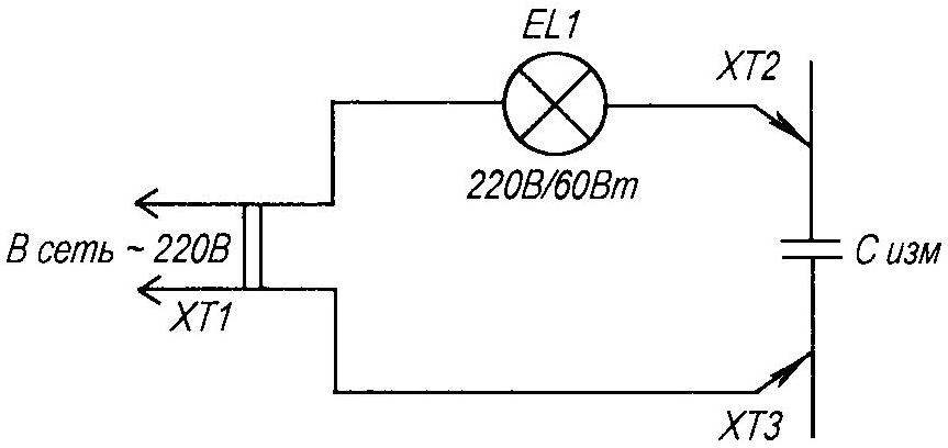
A leaky capacitor is identified using a simple diagram (Fig. 3). In compliance with safety measures (the circuit is galvanically connected to the household network), we connect the capacitor being tested into the circuit. The indicator lamp should not light up - the glow indicates the presence of a leak. Check time is 15 - 30 minutes (in doubtful cases - up to 1 hour). Despite the somewhat barbaric method of testing, it is practically safe for the capacitor. During operation, it is subjected to heavy loads. Thus, I identified thirteen capacitors with obvious leaks, four of them in blocks that worked normally on single-cylinder engines, but failed in the Izha circuit. Replacing capacitors in KET-1A is not difficult - the unit can be easily disassembled. The same replacement performed by 252.3734 is more difficult. First, remove the porous mass filling the housing by boiling the switch in boiling water for 15 - 20 minutes. Then we carefully pluck out the filler with tweezers. By pulling the connectors, we remove the board and gain access to the printed circuit board. You can, of course, replace a faulty device with a similar one, but there is no guarantee that the new one will not fail soon either (see the reason above), so I recommend replacing it with capacitors like K73-17 1.0 μF/ 400 V (or even better, 4x0.47 μF/ 630V). Two capacitors are normally located on the board. We seal the block by filling it with construction foam or a rubber plate cut to size. I would warn you against using various auto sealants - their active components will eventually destroy the copper traces of the board. In order to ensure maximum reliability of the device, I consider metal-paper capacitors of the MBG, MBGP, MBGCh types (the letter G indicates the design of the device), designed for a voltage of 400 - 630 V, as a “no alternative” option. The only problem in this case is the dimensions. A compromise option in the circuit for “Izh-Yu” is possible: we reduce the value of C2 to 1 μF. This will ensure its guaranteed charge in half a revolution of the crankshaft.
The remaining elements of the device usually do not cause any particular complaints. S1 (K73-15) is quite reliable. I advise you to replace diodes VD1, VD4 with KD226G (with a yellow ring) VD3 is practically “indestructible”. It happens that the VS1 thyristor changes its characteristics (the engine starts to start in the opposite direction) - this can be eliminated by replacing it with a KU202N or (even better) with a T122-20-10. It is extremely rare for KU221G (KU240A1) to fail. Replacing the SCR involves selecting the minimum control current. This ignition circuit is very demanding on this parameter. I carry out the selection using the circuit shown in Figure 4. Moving the R1 slider from bottom to top, we use the milliammeter PA1 to note the opening current of the test SCR VS1 at the beginning of the glow of the EL1 lamp. For use, we select specimens with a control current I = 1 - 8mA. Unfortunately, there are SCRs with increased leakage current. This parameter is checked according to the diagram shown in Figure 3. The glow of the lamp will indicate a malfunction of the device.
The BKS restored in this way is suitable for further use in the ignition system of both single- and two-cylinder motorcycles.
D. RASKAZOV, Kashira
Noticed a mistake? Select it and click Ctrl+Enter to let us know.
Creative discoveries of craftsmen from Karelia.
The article talks about the designs of homemade equipment created by a craftsman from Karelia A.A. Koshkarov.
Fisherman's "airboat"
Photos, drawings and descriptions of snowmobiles with an engine from the Buran snowmobile.
Caterpillar on a chain.
Description of one of the propulsion power drive options for tracked motor vehicles and all-terrain vehicles.
Gardening "trifles".
Ways to use old computer parts in your garden.
Vegetable "kindergarten".
One of the options for a garden greenhouse with walls made of window frames.
Stove fireplace.
End of the article “MK” No. 12 for 2007.
Universal pencil.
Description of the design of a pencil with a 2-sided collet.
Adjustable stool.
Homemade stool with height adjustment.
Well, a very simple lathe!
Small lathe for wood processing.
Mosquito with feathers.
Homemade toy helicopter.
Economizer for household appliances.
Energy saving device for household appliances.
Load store.
Schematic diagram of a load store from 1 to 100 ohms.
The battery died - ingenuity came to the rescue.
Electrical circuit of a simple charger for a car battery.
Chinese synthesizer.
Tips and tricks for programming your synthesizer yourself.
"Electromine" for rats.
Description of the design of an electronic mousetrap.
"Flying wing" in a container.
Model of an S4A class flying wing rocket plane.
Combat "WASP".
Detailed description anti-aircraft missile system"WASP".
BMW's roof is going...
Detailed review of the 2007 BMW 335i Convertable.
Britain dresses in armor.
Interesting facts about the large armored cruisers of Britain.
A quarter of a century in service.
A story about the American aircraft Douglas A-26 Invader.

A motorcycle for first-time travelers.
Drawings and diagrams of a simple wheeled ski snowmobile.
The bearing has a place.
One of the options for a universal seat for a ball bearing.
“Pear” instead of lungs.
The process of making a simple pump for pumping gasoline.
Would the tent be durable?
The original design of a tourist tent with modified geometry.
Bike tube - any kind.
An option for joining a bicycle tube using an external and internal mandrel.
The stove... in my pocket.
Homemade portable camping stove.
Easel - from the usual.
Description of a dismountable machine for carrying a tourist backpack.
Behind the wall is a wardrobe and a bed.
The article presents a drawing of built-in furniture for a country attic.
Secret column.
Design of a built-in cabinet-column for the electric meter of a private house.
We cut it out...on a sewing machine.
Stationary jigsaw for wood from a sewing machine.
Barrier to interference.
Description of the design of a low-frequency protective filter for a 220 volt network.
"Firebird" on LEDs.
Gift souvenir “Firebirds” using LEDs.
Automated calls.
Homemade machine for making school bells.
Automatic charging machine for NI-CD batteries.
Schematic diagram and operating principle of an automatic charger for NI-CD batteries.
Radio-controlled seiner.
Description of the original designs of a radio-controlled model of a fishing boat.
A quarter of a century in service.
End of article “M-K” No. 1 for 2008.
New uniform for Ulan.
History of creation, technical data, drawings and photographs of the Japanese car
Mitsubishi Lancer 2007.
BTR-T from a tank.
Detailed description, basic data, modifications, drawings and photographs of the BTR-T heavy armored personnel carrier.

Plow, mow and throw haystacks
Detailed description of a homemade tractor based on a shortened frame from a GAZ-52 car.
"Mini seiner" for a fisherman.
Construction of an amateur radio-controlled boat model fishing For delivery
in fishing places for bait and fishing gear.
Collapsible but durable.
Drawings, diagrams and assembly procedure for a collapsible wooden bed.
Support will correct mistakes.
Description of the original design of embedded foundation supports with transition wedges
or spherical rings.
Bolt Express.
The design of a multifunctional bolt and nut that will facilitate the installation of mounted metal structures.
Folding grill.
Description of a homemade folding barbecue.
The clown is wooden, but as if alive.
A short overview of the process of making an articulated clown figurine.
The aquarium is under control.
The article presents diagrams of various sensors for monitoring water transparency in an aquarium.
Headlight switch indicator.
Schematic diagram and principle of operation of an electronic signaling device for a car.
Power supply overload indicator.
Schemes and designs of various current overload alarms.
A bolt from the blue.
History of creation, technical data, drawings and photographs of the first domestic missile fighter-interceptor BI-1.
S8F class rocket model.
Drawings, diagrams and assembly procedure for a homemade model-copy of the BI-1 aircraft.
All-weather and missile-carrying firstborn.
Detailed description, flight characteristics, modifications, drawings and photographs of the domestic fighter interceptor MiG-17PF U.
ZAZ: from Tavria to Slavuta.
Interesting facts from the history of creation, technical data, drawings and photographs of front-wheel drive cars of the Zaporozhye Automobile Plant.

Airmobile paraglider.
Detailed description, assembly process, drawings and photographs of a homemade four-wheeled paramotor trolley with a propeller-driven power plant.
And one, and two.
The article describes in detail the process of making a homemade three-wheeled velomobile with a front driving steering wheel.
Winter tourist shelter.
Description of the original design of a six-person tent with stove heating.
Velovyuk with “pockets”.
A short overview of the spacious cargo box for a bicycle.
Heating elements are not afraid of scale.
The article describes in detail the design of an electric heater with an oil heat exchanger.
Modest, but strong.
Drawings, diagrams and assembly procedure for a homemade mobile universal table.
"Papakha" for a well.
Design of an original canopy for a well.
Circular spotlight.
The article describes in detail the designs of lamps with a rotating reflector.
Flying on a horse.
The design of a homemade original children's swing.
A restful sleep is guaranteed.
Schematic diagram and principle of operation of a device for protecting against flying insects.
From dusk to dawn.
Device for automatically turning on outdoor lighting.
First step into kiting.
Description of a method for manufacturing an aerobatic kite-hang glider.
Su-17: bomber and fighter.
Detailed description, flight characteristics, drawings and photographs of the SU-17 fighter-bomber.
"Hetzer" - tank destroyer.
History of creation, technical data, drawings and photographs German self-propelled guns"Hetzer".
Italian "mouse".
Detailed description, basic data, drawings and photographs of the Italian car FIA T-500 Topolino.

"Fish" under sail.
Detailed description, assembly process, drawings and photographs of a homemade pleasure float collapsible catamaran.
Hallway set.
Description of a simple and easy-to-make living room set.
Strongman in the branches.
The process of making pruners for cutting high branches.
"Defender" of radio equipment.
The article presents a diagram of a device that is designed for “soft” switching on of various consumers.
Freeze, detail!
Description of methods for securing parts of various configurations.
The light turns on the sound.
Description of a simple buzzer circuit.
Counter in everyday life.
A short overview of the everyday use of an industrial electromechanical meter.
"Controller" of the DC network.
Homemade power consumption monitoring device.
“Sports equipment” from Novy Oskol.
For fans of aircraft modeling, a diagram of the S9A class rotochute model is presented.
Amphibious cargo vehicle K-61.
History of creation, basic data, drawings and photographs of the K-61 tracked floating conveyor.
"Sea Serpent" for India.
Detailed description, flight characteristics, drawings and photographs of the basic anti-submarine aircraft Il=38.
The second birth of the “five hundredth”.
The “Car Show” section talks about the Italian small car Fiat-500 Nuova.

Biplane Chernikov.
Detailed description, assembly process, drawings and photographs of a homemade single-seat aircraft.
Catamaran on mattresses.
A short review of a homemade pleasure craft.
Column for flowers.
Drawings, diagrams and assembly procedure for an original flower stand.
Pipe by pipe through pipe.
The article describes in detail the design of a device for bending pipes and rods.
DIY jewelry.
The article talks about how to make openwork jewelry from copper wire with your own hands.
Miracle burner.
Description of a simple and easy-to-make liquid fuel burner.
Repair of motorcycle ignition switches.
Tips and tricks for DIY repair of motorcycle ignition switches.
And a heavenly sound will flow.
The article talks about how to improve the sound of inexpensive active computers.
acoustic systems.
Second date with Baikonur.
A detailed story about the first Asian Open Championship in rocket and space models.
Rocket plane pilot Menshikov.
Drawings, diagrams and assembly procedure for the S4A class rocket plane model.
Light tank T-70.
Interesting facts from the history of the creation and combat use of the T-70M light tank.
Winged "Dolphin".
History of creation, basic data, drawings and photographs of the Aero L-29 training aircraft.
Rocket for Storm.
The article presents the main characteristics, drawings, diagrams and photographs of the B-611 anti-aircraft guided missile.

First it was a bicycle, then a moto.
The article describes in detail the process of making a homemade two-seater, four-wheel, two-wheel drive velomobile.
A corner with... a waterfall.
Description of the original designs of a country mini-fountain with a closed water flow cycle.
First aid book.
The article describes in detail the design of a homemade universal bookbinding machine.
Safe power supply.
The article talks about how to connect a 400 Hz transformer to a 220 V (50 Hz) network.
PC resuscitation.
The article describes the main PC malfunctions, their diagnosis and elimination methods.
A “radio operator” rocket plane from England.
The section “In the World of Models” talks about the design of the S8E/P class rocket plane model.
Universal bomber.
Detailed description, flight characteristics, drawings and photographs of the German medium bomber AEG G.IV.
Aviation missile RS-2-US.
History of creation, basic data, drawings and photographs of the RS-2-US guided missile.
Foreign car from Moscow.
Detailed story about passenger car Renault Logan from Avtoframos.

A "tractor" that doesn't plow.
A detailed review of a homemade mini-truck made on the basis of the T-16 tractor.
Underground boxing.
Detailed description, drawings and drawings of a recessed garage-workshop.
Way up.
The article presents calculated data and design elements of an internal spiral staircase for an individual attic house.
The masonry is durable and beautiful.
Description of the simplest device for making brickwork.
There is... a machine on the table.
The article describes in detail the design of a mini tabletop drilling machine.
"Fishing" without water.
Description of an original toy for teenagers that simulates fishing.
Deep metal detector.
The original design of a homemade deep metal detector with two sensors.
The transceiver has a long life.
Description of one of the ways to restore the functionality of the CB MJ-2701 car transceiver.
Aerobatics in a line.
The section “In the World of Models” talks about the design of a cord flight training model of an aircraft.
BMP-2 infantry fighting vehicle.
History of the creation, drawings and photographs of the domestic infantry fighting vehicle BMP-2.
Rockets for the Circle.
History of creation, main characteristics, drawings and photographs of the 3M8M anti-aircraft guided missile.
People's airliner Il-18.
Detailed description, basic data, modifications, drawings and photographs of the Il-18 aircraft.

Cargo tandem.
Detailed description, assembly process, drawings and photographs of a homemade mini-truck with a breakable frame.
All-terrain vehicle tires.
The article talks about a method for producing lightweight tires for amateur designs from standard automotive tires.
Chair made from a mattress.
A short review of a homemade floor chair-mattress.
Air seller.
The article describes the design of a tabletop compressor unit.
Universal pots.
Description of a method for decorating a flower pot using plywood plates.
More about the “drunk” fence.
Description of the original picket fence designs.
Cardboard gymnast.
The article talks about how to make a dynamic gymnast toy on the horizontal bar with your own hands.
Invisible watchman.
Schematic diagram and procedure for assembling a car security system based on two radio stations.
Flying... corrugated cardboard.
The section “In the World of Models” talks about the design of a glider model made from corrugated cardboard packaging.
In the cloudless sky of Spain.
Detailed description, flight characteristics, drawings and photographs domestic aircraft I-16.
Conquest of the Angara.
History of creation, technical data, drawings and photographs of an anti-aircraft guided missile
B-860PV "Angara".
Unforgettable "four hundred and eighth".
History of creation, basic data, drawings and photographs of a domestic car
"Moskvich-408".

Crawler... motorcycle.
Detailed description, assembly process, drawings and photographs of a homemade motorcycle with tracks on two rear wheels.
We are improving car alarms.
The article describes how to upgrade the Mongoos Duplex 3D security device.
And yet, how much is in the tank?
A short overview of the hydrostatic fuel level indicator of a motorcycle.
Pipe for a gas boiler.
The article presents the design of an insulated chimney with a damper and a condensate drain.
Curved legs? It's simple!
Option for making figured legs for furniture.
Sheath all sheaths at once.
Design features and assembly process of a tabletop wooden block rack for kitchen knives.
Tabletop miniature.
Detailed drawings and drawings for self-production of a miniature tabletop
drilling machine.
We are learning Morse code.
Description of the original designs of a simulator for training in the reception and transmission of telegraph signals.
"Hawk" is the story of one hawk.
Interesting facts from the history of the creation and combat use of the American Hawk anti-aircraft guided missile.
In the cloudless sky of Spain.
The final part of the article published in M-K No. 9 for 2008.
Tank destroyer "Jagdtiger".
History of creation, basic data, drawings and photographs of the German self-propelled gun Jagdtiger.

Homestead truck.
Detailed description, drawings, diagrams and photographs of a homemade motorcycle chassis with a body.
"Soft" and "tame" bike.
The article talks about how to upgrade a road bike, making it more comfortable and “softer”.
Between the floor and the ceiling.
A short overview of the process of making a simple wall rack from pipes and boards.
The key is "by how much"?
The article describes in detail socket and box wrenches. Drawings, photographs and tables are presented.
Paper bounce.
Description of the original children's toy made of paper “jumping frog”.
There is a flying boat over the water area.
The section “In the World of Models” talks about the design of a radio-controlled model of a seaplane.
"Counter fire."
History of creation, basic data, drawings and photographs of the domestic long-range missile-carrying bomber Tu-22MZ.
"Wolverine" and "Achilles".
Interesting facts from the history of the creation and combat use of American self-propelled artillery systems M10 and M36.
On the "Volga" wide...
Detailed description, performance characteristics, modifications, drawings and photographs of the legendary domestic car "Volga" GAZ-24.

"Buran" plus.
A detailed description of the conversion of the factory snowmobile "Buran" to a motor pump engine.
Trunk for a foreign car.
The article describes in detail the process of making a homemade trunk for an ISUSU minibus.
Express packaging.
A short review of collapsible paper packaging.
Hallway wall.
The design of a homemade combined wardrobe with a mirror and a hanger.
The paths we choose.
A detailed overview of options for garden paths for a personal plot.
"Shoe" for the New Year's beauty.
Description of the original designs of a metal tripod for a New Year tree.
An indispensable electrician's assistant.
Schematic diagram and assembly procedure for a homemade device for monitoring wire voltage.
“Chelyabinka” by Igor Danilov.
The section “In the World of Models” talks about the design of a model of an SZA class rocket.
“Sliding” over the waves.
Interesting facts from the history of the creation of hovercraft.
The many faces of "Yak".
History of creation, basic data, drawings and photographs of the domestic reconnaissance aircraft Yak-27.
Buzzard fighter.
The article talks about the British biplane fighter Martinside F.4.

