29.06.2020
Flashlight 1 LED. LED flashlight with one battery. Do-it-yourself radio engineering, electronics and circuits. How to disassemble the Lentel GL01 LED rechargeable flashlight
I have long wanted to make myself a miniature and bright flashlight powered by one AA or AAA element. There is even a special one for such purposes. microcircuits, but we have a shortage of them + the toad made me think twice. As a result, this miracle was done:
It shines very brightly. The brightness of the glow almost does not drop if you connect another LED in parallel. The abundance of parts + ease of assembly and configuration will allow you to repeat this design without any problems.

The transformer is wound on a ferrite ring. I took a ring from an old one motherboard. It's very easy to wind. We take two wires of the same length (I used two different-colored wires from the network cable). We put them together and with the folded wire we begin to wind the ring turn to turn. As a result, we get 4 wires, two on each side of the ring. We take one wire at a time different colors on each side and tie them together. It should look something like this:

Side view:

Instead of the BC547C transistor, you can use our domestic KT315. With resistor R1 you can slightly adjust the brightness of the light. A board for this circuit was not developed, in my opinion it is of no use here.
Let's look at LED products, ranging from old 5mm to super-bright ones powerful LEDs the power of which reaches 10 W.
To choose the “right” flashlight for your needs, you need to understand what kinds of LED flashlights there are and their characteristics.
What diodes are used in flashlights?
High-power LED lights started with 5mm sensor devices.
LED flashlights in completely different designs, from pocket to camping, became widespread in the mid-2000s. Their price has dropped noticeably, and the brightness and long service life of a single battery charge have played their role.
 5mm white ultra-bright LEDs consume 20 to 50 mA of current, with a voltage drop of 3.2-3.4 volts. Luminous intensity – 800 mcd.
They perform very well in miniature keychain flashlights. Small size allows you to carry this flashlight with you. They are powered either by “mini-pen” batteries or by several round “tablets”. Often used in flashlight lighters.
These are the types of LEDs that have been installed in Chinese lanterns for many years, but their life is gradually coming to an end.
In search lights when large size reflectors, it is possible to mount dozens of such diodes, but such solutions are gradually fading into the background, and the choice of buyers falls in favor of flashlights with powerful Cree-type LEDs.
 Search light with 5mm LEDs
 These flashlights operate on AA, AAA batteries or rechargeable batteries. They are inexpensive and inferior both in brightness and quality to modern flashlights with more powerful crystals, but more on that below.
IN further development flashlight manufacturers have gone through many options, but the market quality products occupied by flashlights with powerful matrices or discrete LEDs.
What kind of LEDs are used in high-power flashlights?
Powerful flashlights mean modern flashlights various types ranging from those the size of a finger to huge search lights.

In such products, the Cree brand is relevant in 2017. This is the name of an American company. Its products are considered one of the most advanced in the field of LED technology. An alternative is LED from the manufacturer Luminus.
Such things are significantly superior to LEDs from Chinese lanterns.
What Cree LEDs are most commonly installed in flashlights?
Models are called consisting of three or four characters, separated by a hyphen. So diodes Cree XR-E, XR-G, XM-L, XP-E. Models XP-E2, G2 are most often used for small flashlights, while XM-L and L2 are very versatile.
They are used starting from the so-called. EDC flashlights (everyday carry) range from small flashlights smaller than the palm of your hand to large, serious search flashlights.
Let's look at the characteristics of high-power LEDs for flashlights.
| Name | Cree XM-L T6 | Cree XM-L2 | Cree XP-G2 | Cree XR-E |
| Photo |  |
|||
| U, V | 2,9 | 2,85 | 2,8 | 3,3 |
| I, mA | 700 | 700 | 350 | 350 |
| P, W | 2 | 2 | 1 | 1 |
| Operating temperature, °C | ||||
| Luminous flux, Lm | 280 | 320 | 145 | 100 |
| Illumination angle, ° | 125 | 125 | 115 | 90 |
| Color rendering index, Ra | 80-90 | 70-90 | 80-90 | 70-90 |
The main characteristic of LEDs for flashlights is luminous flux. The brightness of your flashlight and the amount of light that the source can provide depends on it. Different LEDs, consuming the same amount of energy, can differ significantly in brightness.
Let's look at the characteristics of LEDs in large floodlight flashlights :
| Name | ||||
| Photo |  |  |  |  |
| U, V | 5,7; 8,55; 34,2; | 6; 12; | 3,6 | 3,5 |
| I, mA | 1100; 735; 185; | 2500; 1250 | 5000 | 9000...13500 |
| P, W | 6,3 | 8,5 | 18 | 20...40 |
| Operating temperature, °C | ||||
| Luminous flux, Lm | 440 | 510 | 1250 | 2000...2500 |
| Illumination angle, ° | 115 | 120 | 100 | 90 |
| Color rendering index, Ra | 70-90 | 80-90 | 80-90 |
Sellers often do not indicate the full name of the diode, its type and characteristics, but an abbreviated, slightly different alphanumeric marking:
- For XM-L: T5; T6; U2;
- XP-G: R4; R5; S2;
- XP-E: Q5; R2; R;
- for XR-E: P4; Q3; Q5; R.
The flashlight may be called “EDC T6 Flashlight”, there is more than enough information in such brevity.
Flashlight repair
Unfortunately, the price of such flashlights is quite high, as are the diodes themselves. And it is not always possible to purchase a new flashlight in case of a breakdown. Let's figure out how to change the LED in a flashlight.
To repair a flashlight, you need a minimum set of tools:
- Soldering iron;
- flux;
- solder;
- screwdriver;
- multimeter
To get to the light source you need to unscrew the head of the flashlight; it is usually attached to a threaded connection.

In diode test or resistance measurement mode, check the serviceability of the LED. To do this, touch the black and red probes to the LED terminals, first in one position, and then swap the red and black ones.

If the diode is working properly, then in one of the positions there will be low resistance, and in the other - high. This way you determine that the diode is working and conducts current in only one direction. The diode may emit faint light during testing.
Otherwise, in both positions there will be short circuit or high resistance (open). Then you need to replace the diode in the flashlight.

Now you need to unsolder the LED from the flashlight and, observing the polarity, solder in a new one. Be careful when choosing an LED, consider its current consumption and the voltage for which it is designed.
If you neglect these parameters, in the best case the flashlight will quickly dry up, in the worst case the driver will fail.
A driver is a device for powering an LED with a stabilized current from different sources. Drivers are manufactured industrially for power supply from a 220 volt network, from a car electrical network - 12-14.7 volts, from Li-ion batteries, for example, size 18650. Most powerful flashlights are equipped with a driver.
Increasing the power of the flashlight
If you are not satisfied with the brightness of your flashlight or you have figured out how to replace the LED in a flashlight and want to upgrade it, before buying heavy-duty models, study the basic principles of LED operation and the limitations in their operation.
 Diode matrices do not like overheating - this is the main postulate! And replacing the LED in a flashlight with a more powerful one can lead to this situation. Pay attention to models in which more powerful diodes are installed and compare them with yours; if they are similar in size and design, change them.
If your flashlight is smaller, additional cooling will be required. We wrote more about making radiators with our own hands.
If you try to install such a giant as the Cree MK-R into a miniature keychain flashlight, it will quickly fail from overheating and it will be a waste of money. A slight increase in power (a couple of watts) is acceptable without upgrading the flashlight itself.
Otherwise, the process of replacing the brand of LED in a flashlight with a more powerful one is described above.
Police lights
 LED Police flashlight with shocker
 Such lanterns shine brightly and can act as a means of self-defense. However, they also have problems with LEDs.
How to replace the LED in a Police flashlight
The wide range of models is very difficult to cover in one article, but general recommendations for repairs can be given.
- When repairing a flashlight with a stun gun, be careful, preferably use rubber gloves to avoid electric shock.
- Flashlights with dust and moisture protection are assembled on large quantities screws They differ in length, so make notes from where you unscrewed this or that screw.
- The optical system of the Police flashlight allows you to adjust the diameter of the light spot. When disassembling the body, make marks on the position in which the parts were before removal, otherwise it will be difficult to put the unit with the lens back.
Replacing the LED, voltage converter unit, driver, and battery is possible using a standard soldering kit.
What kind of LEDs are used in Chinese lanterns?
Many products are now purchased on Aliexpress, where you can find both original products and Chinese copies that do not correspond to the stated description. The price for such devices is comparable to the price of the original.

In a flashlight that claims a Cree LED, it may not actually be there; at best, there will be a diode of a frankly different type, at worst, one that will be difficult to distinguish from the original in appearance.
 What might this entail? Cheap LEDs are made in low-tech conditions and do not produce the declared power. They have low efficiency, which is why they have increased heating of the case and crystal. As has already been said, overheating is the most evil enemy for LED devices.
This happens because when heated, the current through the semiconductor increases, as a result of which the heating becomes even stronger, the power is released even more, and this avalanche-like leads to breakdown or breakage of the LED.
If you try and spend time searching for information, you can determine the originality of the product.
 Compare the original and fake cree
 LatticeBright is a Chinese LED manufacturer that makes products very similar to Cree, probably a coincidence of design thought (sarcasm).
 Comparison of the Chinese copy and the original Cree
 On the substrates these clones look like this. You can notice the variety of shapes of LED substrates produced in China.
 Detecting counterfeit by LED substrate
 Counterfeits are made quite skillfully; many sellers do not indicate this “brand” in the product description and where the LEDs for flashlights are made. The quality of such diodes is not the worst among Chinese junk, but it is also far from the original.
Installing an LED instead of an incandescent lamp
Many people have horse races or incandescent lamps collecting dust in old things, and you can easily turn it into LED. For this, there are either ready-made solutions or homemade ones.
Using a broken light bulb and LEDs, with a little ingenuity and solder, you can make a great replacement.
In this case, an iron barrel is needed to improve heat removal from the LED. Next you need to solder all the parts to each other and secure with glue.
When assembling, be careful - avoid shorting the leads; hot glue or heat shrink tubing will help with this. The central contact of the lamp must be unsoldered - a hole will form. Pass the resistor lead through it.
Next you need to solder the free lead of the LED to the base, and the resistor to the central contact. For a voltage of 12 volts, a 500 Ohm resistor is needed, and for a voltage of 5 V – 50-100 Ohms, for power supply from a Li-ion 3.7V battery – 10-25 Ohms.
 How to make an LED lamp from an incandescent lamp
 Selecting an LED for a flashlight is much more difficult than replacing it. It is necessary to take into account a lot of parameters: from brightness and dispersion angle to heating of the case.
In addition, we must not forget about the power supply for the diodes. If you master everything described above, your devices will shine for a long time and with high quality!
A flashlight is a thing that is needed in every home. Sometimes the light goes out, or you have to go into a dark basement. In general, such a thing should always be at hand. And it is desirable that he could for a long time stored without recharging. Otherwise you will find out about dead batteries at the most inopportune moment :) For this we will use lithium ion battery, which has a very low self-discharge. In general, the flashlight lay idle for a long time DiK-5 euro. It uses a 2.5V 0.15A incandescent light bulb as a light source, the power source of which is 3 round disk elements D-0.26. The flashlight initially held a charge for about an hour of continuous operation, but now it doesn’t hold a charge at all and the batteries have oxidized. The light bulb doesn't shine much. In short, you can’t call it a good flashlight.
I disassembled it, took out all the insides and cut out with an engraver the plastic partitions that secure the batteries. Next, it was decided to replace the light bulb with a 1W LED (4200k), which was removed from the spotlight lamp because it was a bit cramped there, and the reflector was bad.


Next I borrowed from the broken one cell phone Nokia, which was given to me for spare parts, battery and connector charger. I calculated the resistor for the LED, since the battery produces 3.6V, and the LED voltage is 3V (in my case).


Since the LED gets hot, it needs cooling. I cut out a piece of aluminum and fixed it on one half of the body, drilled two holes in it for the legs of the LED and inserted it, after insulating each leg with heat-shrink tubing. The photo below shows, for comparison, the appearance of a conventional lamp and an LED in a reflector.

Between the heatsink and the LED I lubricated the area with thermal paste. The toggle switch was taken from a fluorescent lamp. Next, I soldered everything and fixed the charging connector with hot-melt glue. The battery, although it is 860mAh, lasts for 2.5-3 hours of continuous operation.
Making your own LED flashlight
LED flashlight with 3-volt converter for LED 0.3-1.5V 0.3-1.5
VLEDFlashLight
Typically, a blue or white LED requires 3 - 3.5v to operate; this circuit allows you to power a blue or white LED with low voltage from one AA battery.Normally, if you want to light up a blue or white LED you need to provide it with 3 - 3.5 V, like from a 3 V lithium coin cell.
Details:
Light-emitting diode
Ferrite ring (~10 mm diameter)
Wire for winding (20 cm)
1kOhm resistor
N-P-N transistor
Battery
Parameters of the transformer used:
The winding going to the LED has ~45 turns, wound with 0.25mm wire.
The winding going to the base of the transistor has ~30 turns of 0.1mm wire.
The base resistor in this case has a resistance of about 2K.
Instead of R1, it is advisable to install a tuning resistor, and achieve a current through the diode of ~22 mA; with a fresh battery, measure its resistance, then replacing it with a constant resistor of the obtained value.
The assembled circuit should work immediately.
There are only 2 possible reasons why the scheme will not work.
1. the ends of the winding are mixed up.
2. too few turns of the base winding.
Generation disappears with the number of turns<15.
 Place the wire pieces together and wrap them around the ring.
Connect the two ends of different wires together.
The circuit can be placed inside a suitable housing.
The introduction of such a circuit into a flashlight operating on 3V significantly extends the duration of its operation from one set of batteries.
Option to make the flashlight powered by one 1.5V battery.


The transistor and resistance are placed inside the ferrite ring


The white LED runs on a dead AAA battery.
Modernization option "flashlight - pen"
 The excitation of the blocking oscillator shown in the diagram is achieved by transformer coupling at T1. The voltage pulses arising in the right (according to the circuit) winding are added to the voltage of the power source and are supplied to the LED VD1. Of course, it would be possible to eliminate the capacitor and resistor in the base circuit of the transistor, but then failure of VT1 and VD1 is possible when using branded batteries with low internal resistance. The resistor sets the operating mode of the transistor, and the capacitor passes the RF component.
The circuit used a KT315 transistor (as the cheapest, but any other with a cutoff frequency of 200 MHz or more) and a super-bright LED were used. To make a transformer, you will need a ferrite ring (approximate size 10x6x3 and permeability of about 1000 HH). The wire diameter is about 0.2-0.3 mm. Two coils of 20 turns each are wound on the ring.
If there is no ring, then you can use a cylinder of similar volume and material. You just have to wind 60-100 turns for each of the coils.
Important point : you need to wind the coils in different directions.
Photos of the flashlight:
the switch is in the "fountain pen" button, and the gray metal cylinder conducts current.

We make a cylinder according to the standard size of the battery.


It can be made from paper, or use a piece of any rigid tube.
We make holes along the edges of the cylinder, wrap it with tinned wire, and pass the ends of the wire into the holes. We fix both ends, but leave a piece of conductor at one end so that we can connect the converter to the spiral.
A ferrite ring would not fit into the lantern, so a cylinder made of a similar material was used.

A cylinder made from an inductor from an old TV.
The first coil is about 60 turns.
Then the second one swings in the opposite direction again for 60 or so. The coils are held together with glue.
Assembling the converter:

Everything is located inside our case: We solder the transistor, the capacitor, the resistor, solder the spiral on the cylinder, and the coil. The current in the coil windings must go in different directions! That is, if you wound all the windings in one direction, then swap the leads of one of them, otherwise generation will not occur.
The result is the following:

We insert everything inside, and use nuts as side plugs and contacts.
We solder the coil leads to one of the nuts, and the VT1 emitter to the other. Glue it. We mark the conclusions: where we have the output from the coils we put “-”, where the output from the transistor with the coil we put “+” (so that everything is like in a battery).
Now you need to make a “lampodiode”.

Attention: There should be a minus LED on the base.
Assembly:
 As is clear from the figure, the converter is a “substitute” for the second battery. But unlike it, it has three points of contact: with the plus of the battery, with the plus of the LED, and the common body (through the spiral).
Its location in the battery compartment is specific: it must be in contact with the positive of the LED.
Modern flashlightwith LED operating mode powered by constant stabilized current.

The current stabilizer circuit works as follows:
When power is applied to the circuit, transistors T1 and T2 are locked, T3 is open, because an unlocking voltage is applied to its gate through resistor R3. Due to the presence of inductor L1 in the LED circuit, the current increases smoothly. As the current in the LED circuit increases, the voltage drop across the R5-R4 chain increases; as soon as it reaches approximately 0.4V, transistor T2 will open, followed by T1, which in turn will close the current switch T3. The increase in current stops, a self-induction current appears in the inductor, which begins to flow through diode D1 through the LED and a chain of resistors R5-R4. As soon as the current decreases below a certain threshold, transistors T1 and T2 will close, T3 will open, which will lead to a new cycle of energy accumulation in the inductor. In normal mode, the oscillatory process occurs at a frequency of the order of tens of kilohertz.
About details:
Instead of the IRF510 transistor, you can use the IRF530, or any n-channel field-effect switching transistor with a current of more than 3A and a voltage of more than 30 V.
Diode D1 must have a Schottky barrier for a current of more than 1A; if you install even a regular high-frequency type KD212, the efficiency will drop to 75-80%.
The inductor is homemade; it is wound with a wire no thinner than 0.6 mm, or better - with a bundle of several thinner wires. About 20-30 turns of wire per armor core B16-B18 are required with a non-magnetic gap of 0.1-0.2 mm or close from 2000NM ferrite. If possible, the thickness of the non-magnetic gap is selected experimentally according to the maximum efficiency of the device. Good results can be obtained with ferrites from imported inductors installed in switching power supplies, as well as in energy-saving lamps. Such cores have the appearance of a spool of thread and do not require a frame or a non-magnetic gap. Coils on toroidal cores made of pressed iron powder, which can be found in computer power supplies (the output filter inductors are wound on them), work very well. The non-magnetic gap in such cores is evenly distributed throughout the volume due to the production technology.
The same stabilizer circuit can be used in conjunction with other batteries and galvanic cell batteries with a voltage of 9 or 12 volts without any change in the circuit or cell ratings. The higher the supply voltage, the less current the flashlight will consume from the source, its efficiency will remain unchanged. The operating stabilization current is set by resistors R4 and R5.
If necessary, the current can be increased to 1A without the use of heat sinks on the parts, only by selecting the resistance of the setting resistors.
The battery charger can be left “original” or assembled according to any of the known schemes, or even used externally to reduce the weight of the flashlight.
LED flashlight from calculator B3-30
The converter is based on the circuit of the B3-30 calculator, the switching power supply of which uses a transformer only 5 mm thick and having two windings. Using a pulse transformer from an old calculator made it possible to create an economical LED flashlight.
The result is a very simple circuit.
 The voltage converter is made according to the circuit of a single-cycle generator with inductive feedback on transistor VT1 and transformer T1. The pulse voltage from winding 1-2 (according to the circuit diagram of the B3-30 calculator) is rectified by diode VD1 and supplied to the ultra-bright LED HL1. Capacitor C3 filter. The design is based on a Chinese-made flashlight designed to install two AA batteries. The converter is mounted on a printed circuit board made of one-sided foil fiberglass 1.5 mm thickFig.2dimensions that replace one battery and are inserted into the flashlight instead. A contact made of double-sided foil-coated fiberglass with a diameter of 15 mm is soldered to the end of the board, marked with a “+” sign; both sides are connected by a jumper and tinned with solder.
After installing all the parts on the board, the “+” end contact and the T1 transformer are filled with hot-melt adhesive to increase strength. A variant of the lantern layout is shown inFig.3and in a particular case depends on the type of flashlight used. In my case, no modifications to the flashlight were required, the reflector has a contact ring to which the negative terminal of the printed circuit board is soldered, and the board itself is attached to the reflector using hot-melt adhesive. The printed circuit board assembly with the reflector is inserted instead of one battery and clamped with a lid.
 The voltage converter uses small-sized parts. Resistors type MLT-0.125, capacitors C1 and C3 are imported, up to 5 mm high. Diode VD1 type 1N5817 with a Schottky barrier; in its absence, you can use any rectifier diode that has suitable parameters, preferably germanium due to the lower voltage drop across it. A correctly assembled converter does not need adjustment unless the transformer windings are reversed; otherwise, swap them. If the above transformer is not available, you can make it yourself. Winding is carried out on a ferrite ring of standard size K10*6*3 with a magnetic permeability of 1000-2000. Both windings are wound with PEV2 wire with a diameter of 0.31 to 0.44 mm. The primary winding has 6 turns, the secondary winding has 10 turns. After installing such a transformer on the board and checking its functionality, it should be secured to it using hot-melt adhesive.
Tests of a flashlight with an AA battery are presented in Table 1.
During testing, the cheapest AA battery was used, costing only 3 rubles. The initial voltage under load was 1.28 V. At the output of the converter, the voltage measured on the super-bright LED was 2.83 V. The LED brand is unknown, diameter 10 mm. The total current consumption is 14 mA. The total operating time of the flashlight was 20 hours of continuous operation.
When the battery voltage drops below 1V, the brightness drops noticeably.
| Time, h | V battery, V | V conversion, V |
| 0 | 1,28 | 2,83 |
| 2 | 1,22 | 2,83 |
| 4 | 1,21 | 2,83 |
| 6 | 1,20 | 2,83 |
| 8 | 1,18 | 2,83 |
| 10 | 1,18 | 2.83 |
| 12 | 1,16 | 2.82 |
| 14 | 1,12 | 2.81 |
| 16 | 1,11 | 2.81 |
| 18 | 1,11 | 2.81 |
| 20 | 1,10 | 2.80 |
Homemade LED flashlight
The basis is a VARTA flashlight powered by two AA batteries:
Since diodes have a highly nonlinear current-voltage characteristic, it is necessary to equip the flashlight with a circuit for working with LEDs, which will ensure constant brightness as the battery discharges and will remain operational at the lowest possible supply voltage.
The basis of the voltage stabilizer is a micro-power step-up DC/DC converter MAX756.
According to the stated characteristics, it operates when the input voltage is reduced to 0.7V.
Connection diagram - typical:

 Installation is carried out using a hinged method.
Electrolytic capacitors - tantalum CHIP. They have low series resistance, which slightly improves efficiency. Schottky diode - SM5818. The chokes had to be connected in parallel, because there was no suitable denomination. Capacitor C2 - K10-17b. LEDs - super bright white L-53PWC "Kingbright".
As can be seen in the figure, the entire circuit easily fits into the empty space of the light-emitting unit.
The output voltage of the stabilizer in this circuit is 3.3V. Since the voltage drop across the diodes in the nominal current range (15-30mA) is about 3.1V, the extra 200mV had to be extinguished by a resistor connected in series with the output.
In addition, a small series resistor improves load linearity and circuit stability. This is due to the fact that the diode has a negative TCR, and when warmed up, its forward voltage drop decreases, which leads to a sharp increase in the current through the diode when it is powered from a voltage source. There was no need to equalize the currents through parallel-connected diodes - no differences in brightness were observed by eye. Moreover, the diodes were of the same type and taken from the same box.
Now about the design of the light emitter. As can be seen in the photographs, the LEDs in the circuit are not tightly sealed, but are a removable part of the structure.

 The original light bulb is gutted, and 4 cuts are made in the flange on 4 sides (one was already there). 4 LEDs are arranged symmetrically in a circle. The positive terminals (according to the diagram) are soldered onto the base near the cuts, and the negative terminals are inserted from the inside into the central hole of the base, cut off and also soldered. “Lampodiode” is inserted in place of a regular incandescent light bulb.
Testing:
Stabilization of the output voltage (3.3V) continued until the supply voltage was reduced to ~1.2V. The load current was about 100mA (~ 25mA per diode). Then the output voltage began to decrease smoothly. The circuit has switched to a different operating mode, in which it no longer stabilizes, but outputs everything it can. In this mode, it worked up to a supply voltage of 0.5V! The output voltage dropped to 2.7V, and the current from 100mA to 8mA.
A little about efficiency.
 The efficiency of the circuit is about 63% with fresh batteries. The fact is that the miniature chokes used in the circuit have an extremely high ohmic resistance - about 1.5 ohms
The solution is a ring made of µ-permalloy with a permeability of about 50.
40 turns of PEV-0.25 wire, in one layer - it turned out to be about 80 μG. The active resistance is about 0.2 Ohm, and the saturation current, according to calculations, is more than 3A. We change the output and input electrolyte to 100 μF, although without compromising efficiency it can be reduced to 47 μF.
LED flashlight circuiton a DC/DC converter from Analog Device - ADP1110.

Standard typical ADP1110 connection circuit.
This converter chip, according to the manufacturer’s specifications, is available in 8 versions:
| Model | Output voltage |
| ADP1110AN | Adjustable |
| ADP1110AR | Adjustable |
| ADP1110AN-3.3 | 3.3V |
| ADP1110AR-3.3 | 3.3V |
| ADP1110AN-5 | 5 V |
| ADP1110AR-5 | 5 V |
| ADP1110AN-12 | 12 V |
| ADP1110AR-12 | 12 V |
Microcircuits with the indices “N” and “R” differ only in the type of housing: R is more compact.
If you bought a chip with index -3.3, you can skip the next paragraph and go to the “Details” item.
If not, I present to your attention another diagram:

It adds two parts that make it possible to obtain the required 3.3 volts at the output to power the LEDs.
The circuit can be improved by taking into account that LEDs require a current source rather than a voltage source to operate. Changes in the circuit so that it produces 60mA (20 for each diode), and the voltage of the diodes will be set to us automatically, the same 3.3-3.9V.

resistor R1 is used to measure current. The converter is designed in such a way that when the voltage at the FB (Feed Back) pin exceeds 0.22V, it will stop increasing the voltage and current, which means the resistance value R1 is easy to calculate R1 = 0.22V/In, in our case 3.6 Ohm. This circuit helps stabilize the current and automatically select the required voltage. Unfortunately, the voltage will drop across this resistance, which will lead to a decrease in efficiency, however, practice has shown that it is less than the excess that we chose in the first case. I measured the output voltage and it was 3.4 - 3.6V. The parameters of the diodes in such a connection should also be as identical as possible, otherwise the total current of 60 mA will not be distributed equally between them, and we will again get different luminosities.
Details
1. Any choke from 20 to 100 microhenry with a small (less than 0.4 Ohm) resistance is suitable. The diagram shows 47 µH. You can make it yourself - wind about 40 turns of PEV-0.25 wire on a ring of µ-permalloy with a permeability of about 50, size 10x4x5.
2. Schottky diode. 1N5818, 1N5819, 1N4148 or similar. Analog Device DOES NOT RECOMMEND the use of 1N4001
3. Capacitors. 47-100 microfarads at 6-10 volts. It is recommended to use tantalum.
4. Resistors. With a power of 0.125 watts and a resistance of 2 ohms, possibly 300 kohms and 2.2 kohms.
5. LEDs. L-53PWC - 4 pieces.
Voltage converter for powering the DFL-OSPW5111P white LED with a brightness of 30 cd at a current of 80 mA and a radiation pattern width of about 12°.


The current consumed from a 2.41V battery is 143mA; in this case, a current of about 70 mA flows through the LED at a voltage of 4.17 V. The converter operates at a frequency of 13 kHz, the electrical efficiency is about 0.85.
Transformer T1 is wound on a ring magnetic core of standard size K10x6x3 made of 2000NM ferrite.
The primary and secondary windings of the transformer are wound simultaneously (i.e., in four wires).
The primary winding contains - 2x41 turns of wire PEV-2 0.19,
The secondary winding contains 2x44 turns of PEV-2 0.16 wire.
After winding, the terminals of the windings are connected in accordance with the diagram.
Transistors KT529A of the p-n-p structure can be replaced with KT530A of the n-p-n structure, in this case it is necessary to change the polarity of the connection of the battery GB1 and the LED HL1.
The parts are placed on the reflector using wall-mounted installation. Please ensure that there is no contact between the parts and the tin plate of the flashlight, which supplies the minus of the GB1 battery. The transistors are fastened together with a thin brass clamp, which provides the necessary heat removal, and then glued to the reflector. The LED is placed instead of the incandescent lamp so that it protrudes 0.5... 1 mm from the socket for its installation. This improves heat dissipation from the LED and simplifies its installation.
When first turned on, power from the battery is supplied through a resistor with a resistance of 18...24 Ohms so as not to damage the transistors if the terminals of transformer T1 are incorrectly connected. If the LED does not light, it is necessary to swap the extreme terminals of the primary or secondary winding of the transformer. If this does not lead to success, check the serviceability of all elements and correct installation.
Voltage converter for powering an industrial LED flashlight.

Voltage converter to power LED flashlight
 The diagram is taken from the Zetex manual for the use of ZXSC310 microcircuits.
ZXSC310- LED driver chip.
FMMT 617 or FMMT 618.
Schottky diode- almost any brand.
Capacitors C1 = 2.2 µF and C2 = 10 µFfor surface mounting, 2.2 µF is the value recommended by the manufacturer, and C2 can be supplied from approximately 1 to 10 µF
68 microhenry inductor at 0.4 A
 The inductance and resistor are installed on one side of the board (where there is no printing), all other parts are installed on the other. The only trick is to make a 150 milliohm resistor. It can be made from 0.1 mm iron wire, which can be obtained by unraveling the cable. The wire should be annealed with a lighter, thoroughly wiped with fine sandpaper, the ends should be tinned and a piece about 3 cm long should be soldered into the holes on the board. Next, during the setup process, you need to measure the current through the diodes, move the wire, while simultaneously heating the place where it is soldered to the board with a soldering iron.
Thus, something like a rheostat is obtained. Having achieved a current of 20 mA, the soldering iron is removed and the unnecessary piece of wire is cut off. The author came up with a length of approximately 1 cm.
Flashlight on the power source

Rice. 3.Flashlight on a current source, with automatic equalization of current in LEDs, so that LEDs can have any range of parameters (LED VD2 sets the current, which is repeated by transistors VT2, VT3, so the currents in the branches will be the same)
The transistors, of course, should also be the same, but the spread of their parameters is not so critical, so you can take either discrete transistors, or if you can find three integrated transistors in one package, their parameters are as identical as possible. Play around with the placement of the LEDs, you need to choose an LED-transistor pair so that the output voltage is minimal, this will increase the efficiency.
The introduction of transistors leveled out the brightness, however, they have resistance and the voltage drops across them, which forces the converter to increase the output level to 4V. To reduce the voltage drop across the transistors, you can propose the circuit in Fig. 4, this is a modified current mirror, instead of the reference voltage Ube = 0.7V in the circuit in Fig. 3, you can use the 0.22V source built into the converter, and maintain it in the VT1 collector using an op-amp, also built into the converter.

Rice. 4.Flashlight on a current source, with automatic current equalization in LEDs, and with improved efficiency
Because The op-amp output is of the “open collector” type; it must be “pulled up” to the power supply, which is done by resistor R2. Resistances R3, R4 act as a voltage divider at point V2 by 2, so the opamp will maintain a voltage of 0.22*2 = 0.44V at point V2, which is 0.3V less than in the previous case. It is not possible to take an even smaller divider in order to lower the voltage at point V2. a bipolar transistor has a resistance Rke and during operation the voltage Uke will drop on it, in order for the transistor to work correctly V2-V1 must be greater than Uke, for our case 0.22V is quite enough. However, bipolar transistors can be replaced with field-effect transistors, in which the drain-source resistance is much lower, this will make it possible to reduce the divider, so as to make the difference V2-V1 very insignificant.
Throttle.The choke must be taken with minimal resistance, special attention should be paid to the maximum permissible current; it should be about 400 -1000 mA.
The rating doesn't matter as much as the maximum current, so Analog Devices recommends something between 33 and 180 µH. In this case, theoretically, if you do not pay attention to the dimensions, then the greater the inductance, the better in all respects. However, in practice this is not entirely true, because we do not have an ideal coil, it has active resistance and is not linear, in addition, the key transistor at low voltages will no longer produce 1.5A. Therefore, it is better to try several coils of different types, designs and different ratings in order to choose the coil with the highest efficiency and the lowest minimum input voltage, i.e. a coil with which the flashlight will glow for as long as possible.
Capacitors.C1 can be anything. It is better to take C2 with tantalum because It has low resistance, which increases efficiency.
Schottky diode.Any for current up to 1A, preferably with minimal resistance and minimal voltage drop.
Transistors.Any with a collector current of up to 30 mA, coefficient. current amplification of about 80 with a frequency of up to 100 MHz, KT318 is suitable.
LEDs.You can use white NSPW500BS with a glow of 8000 mcd from Power Light Systems.
Voltage transformerADP1110, or its replacement ADP1073, to use it, the circuit in Fig. 3 will need to be changed, take a 760 µH inductor, and R1 = 0.212/60mA = 3.5 Ohm.
Flashlight on ADP3000-ADJ
Options:
Power supply 2.8 - 10 V, efficiency approx. 75%, two brightness modes - full and half.
The current through the diodes is 27 mA, in half-brightness mode - 13 mA.
In order to obtain high efficiency, it is advisable to use chip components in the circuit.
A correctly assembled circuit does not need adjustment.
The disadvantage of the circuit is the high (1.25V) voltage at the FB input (pin 8).
Currently, DC/DC converters with an FB voltage of about 0.3V are produced, in particular from Maxim, on which it is possible to achieve an efficiency above 85%.

Flashlight diagram for Kr1446PN1.

Resistors R1 and R2 are a current sensor. Operational amplifier U2B - amplifies the voltage taken from the current sensor. Gain = R4 / R3 + 1 and is approximately 19. The gain required is such that when the current through resistors R1 and R2 is 60 mA, the output voltage turns on transistor Q1. By changing these resistors, you can set other stabilization current values.
In principle, there is no need to install an operational amplifier. Simply, instead of R1 and R2, one 10 Ohm resistor is placed, from it the signal through a 1 kOhm resistor is supplied to the base of the transistor and that’s it. But. This will lead to a decrease in efficiency. On a 10 Ohm resistor at a current of 60 mA, 0.6 Volt - 36 mW - is dissipated in vain. If an operational amplifier is used, the losses will be:
on a 0.5 Ohm resistor at a current of 60 mA = 1.8 mW + consumption of the op-amp itself is 0.02 mA let at 4 Volts = 0.08 mW
= 1.88 mW - significantly less than 36 mW.
About the components.
Any low-power op-amp with a low minimum supply voltage can work in place of the KR1446UD2; the OP193FS would be better suited, but it is quite expensive. Transistor in SOT23 package. A smaller polar capacitor - type SS for 10 Volts. The inductance of CW68 is 100 μH for a current of 710 mA. Although the cutoff current of the inverter is 1 A, it works fine. It achieved the best efficiency. I selected the LEDs based on the most equal voltage drop at a current of 20 mA. The flashlight is assembled in a housing for two AA batteries. I shortened the space for the batteries to fit the size of AAA batteries, and in the freed-up space I assembled this circuit using wall-mounted installation. A case that fits three AA batteries works well. You will need to install only two, and place the circuit in place of the third.
Efficiency of the resulting device.
Input U I P Output U I P Efficiency
Volt mA mW Volt mA mW %
3.03 90 273 3.53 62 219 80
1.78 180 320 3.53 62 219 68
1.28 290 371 3.53 62 219 59
Replacing the bulb of the “Zhuchek” flashlight with a module from the companyLuxeonLumiledLXHL-NW 98.
We get a dazzlingly bright flashlight, with a very light press (compared to a light bulb).


Rework scheme and module parameters.
StepUP DC-DC converters ADP1110 converters from Analog devices.


Power supply: 1 or 2 1.5V batteries, operability maintained up to Uinput = 0.9V
Consumption:
*with switch open S1 = 300mA
*with switch closed S1 = 110mA
LED Electronic Flashlight
Powered by just one AA or AAA AA battery on a microcircuit (KR1446PN1), which is a complete analogue of the MAX756 (MAX731) microcircuit and has almost identical characteristics.

The flashlight is based on a flashlight that uses two AA size AA batteries as a power source.
The converter board is placed in the flashlight instead of the second battery. A contact made of tinned sheet metal is soldered at one end of the board to power the circuit, and at the other there is an LED. A circle made of the same tin is placed on the LED terminals. The diameter of the circle should be slightly larger than the diameter of the reflector base (0.2-0.5 mm) into which the cartridge is inserted. One of the diode leads (negative) is soldered to the circle, the second (positive) goes through and is insulated with a piece of PVC or fluoroplastic tube. The purpose of the circle is twofold. It provides the structure with the necessary rigidity and at the same time serves to close the negative contact of the circuit. The lamp with the socket is removed from the lantern in advance and a circuit with an LED is placed in its place. Before installation on the board, the LED leads are shortened in such a way as to ensure a tight, play-free fit. Typically, the length of the leads (excluding soldering to the board) is equal to the length of the protruding part of the fully screwed-in lamp base.
The connection diagram between the board and the battery is shown in Fig. 9.2.
Next, the lantern is assembled and its functionality is checked. If the circuit is assembled correctly, then no settings are required.
The design uses standard installation elements: capacitors of the K50-35 type, EC-24 chokes with an inductance of 18-22 μH, LEDs with a brightness of 5-10 cd with a diameter of 5 or 10 mm. Of course, it is possible to use other LEDs with a supply voltage of 2.4-5 V. The circuit has sufficient power reserve and allows you to power even LEDs with a brightness of up to 25 cd!
About some test results of this design.
The flashlight modified in this way worked with a “fresh” battery without interruption, in the on state, for more than 20 hours! For comparison, the same flashlight in the “standard” configuration (that is, with a lamp and two “fresh” batteries from the same batch) worked for only 4 hours.
And one more important point. If you use rechargeable batteries in this design, it is easy to monitor the state of their discharge level. The fact is that the converter on the KR1446PN1 microcircuit starts stably at an input voltage of 0.8-0.9 V. And the glow of the LEDs is consistently bright until the voltage on the battery reaches this critical threshold. The lamp will, of course, still burn at this voltage, but we can hardly talk about it as a real light source.
Rice. 9.2Figure 9.3


The printed circuit board of the device is shown in Fig. 9.3, and the arrangement of elements is in Fig. 9.4.
Turning the flashlight on and off with one button
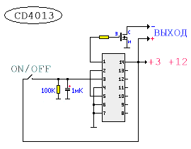
The circuit is assembled using a CD4013 D-trigger chip and an IRF630 field-effect transistor in the “off” mode. the current consumption of the circuit is practically 0. For stable operation of the D-trigger, a filter resistor and capacitor are connected to the input of the microcircuit; their function is to eliminate contact bounce. It is better not to connect unused pins of the microcircuit anywhere. The microcircuit operates from 2 to 12 volts; any powerful field-effect transistor can be used as a power switch, because The drain-source resistance of the field-effect transistor is negligible and does not load the output of the microcircuit.
CD4013A in SO-14 package, analogue of K561TM2, 564TM2
Simple generator circuits.
 Allows you to power an LED with an ignition voltage of 2-3V from 1-1.5V. Short pulses of increased potential unlock the p-n junction. The efficiency of course decreases, but this device allows you to “squeeze” almost its entire resource from an autonomous power source.
Wire 0.1 mm - 100-300 turns with a tap from the middle, wound on a toroidal ring.


LED flashlight with adjustable brightness and Beacon mode
 The power supply of the microcircuit - generator with adjustable duty cycle (K561LE5 or 564LE5) that controls the electronic key, in the proposed device is carried out from a step-up voltage converter, which allows the flashlight to be powered from one 1.5 galvanic cell.
The converter is made on transistors VT1, VT2 according to the circuit of a transformer self-oscillator with positive current feedback.
The generator circuit with adjustable duty cycle on the K561LE5 chip mentioned above has been slightly modified in order to improve the linearity of current regulation.
The minimum current consumption of a flashlight with six super-bright white LEDs L-53MWC from Kingbnght connected in parallel is 2.3 mA. The dependence of the current consumption on the number of LEDs is directly proportional.
The "Beacon" mode, when the LEDs flash brightly at a low frequency and then go out, is implemented by setting the brightness control to maximum and turning the flashlight on again. The desired frequency of light flashes is adjusted by selecting the capacitor SZ.
The performance of the flashlight is maintained when the voltage is reduced to 1.1v, although the brightness is significantly reduced
A field-effect transistor with an insulated gate KP501A (KR1014KT1V) is used as an electronic switch. According to the control circuit, it matches well with the K561LE5 microcircuit. The KP501A transistor has the following limit parameters: drain-source voltage - 240 V; gate-source voltage - 20 V. drain current - 0.18 A; power - 0.5 W
It is permissible to connect transistors in parallel, preferably from the same batch. Possible replacement - KP504 with any letter index. For IRF540 field-effect transistors, the supply voltage of the DD1 microcircuit. generated by the converter must be increased to 10 V
In a flashlight with six L-53MWC LEDs connected in parallel, the current consumption is approximately equal to 120 mA when the second transistor is connected in parallel to VT3 - 140 mA
Transformer T1 is wound on a ferrite ring 2000NM K10-6"4.5. The windings are wound in two wires, with the end of the first winding connected to the beginning of the second winding. The primary winding contains 2-10 turns, the secondary - 2 * 20 turns. Wire diameter - 0.37 mm. grade - PEV-2. The inductor is wound on the same magnetic circuit without a gap with the same wire in one layer, the number of turns is 38. The inductance of the inductor is 860 μH


Converter circuit for LED from 0.4 to 3V- runs on one AAA battery. This flashlight increases the input voltage to the desired voltage using a simple DC-DC converter.


The output voltage is approximately 7 W (depending on the voltage of the installed LEDs).
Building the LED Head Lamp


As for the transformer in the DC-DC converter. You must do it yourself. The image shows how to assemble the transformer.

Another option for converters for LEDs _http://belza.cz/ledlight/ledm.htm


Flashlight with lead-acid sealed battery with charger.
Lead acid sealed batteries are the cheapest currently available. The electrolyte in them is in the form of a gel, so the batteries allow operation in any spatial position and do not produce any harmful fumes. They are characterized by great durability if deep discharge is not allowed. Theoretically, they are not afraid of overcharging, but this should not be abused. Rechargeable batteries can be recharged at any time without waiting for them to be completely discharged.
Lead-acid sealed batteries are suitable for use in portable flashlights used in the household, in summer cottages, and in production.

Fig.1. Electric flashlight circuit
The electrical circuit diagram of a flashlight with a charger for a 6-volt battery, which makes it possible in a simple way to prevent deep discharge of the battery and, thus, increase its service life, is shown in the figure. It contains a factory-made or home-made transformer power supply and a charging and switching device mounted in the flashlight body.
In the author's version, a standard unit intended for powering modems is used as a transformer unit. The output alternating voltage of the unit is 12 or 15 V, the load current is 1 A. Such units are also available with built-in rectifiers. They are also suitable for this purpose.
The alternating voltage from the transformer unit is supplied to the charging and switching device, which contains a plug for connecting the charger X2, a diode bridge VD1, a current stabilizer (DA1, R1, HL1), a battery GB, a toggle switch S1, an emergency switch S2, an incandescent lamp HL2. Each time the toggle switch S1 is turned on, the battery voltage is supplied to relay K1, its contacts K1.1 close, supplying current to the base of transistor VT1. The transistor turns on, passing current through the HL2 lamp. Turn off the flashlight by switching toggle switch S1 to its original position, in which the battery is disconnected from the winding of relay K1.
The permissible battery discharge voltage is selected at 4.5 V. It is determined by the switching voltage of relay K1. You can change the permissible value of the discharge voltage using resistor R2. As the resistor value increases, the permissible discharge voltage increases, and vice versa. If the battery voltage is below 4.5 V, the relay will not turn on, therefore, no voltage will be supplied to the base of the transistor VT1, which turns on the HL2 lamp. This means the battery needs charging. At a voltage of 4.5 V, the illumination produced by the flashlight is not bad. In case of emergency, you can turn on the flashlight at low voltage with the S2 button, provided that you first turn on the S1 toggle switch.
A constant voltage can also be supplied to the input of the charger-switching device, without paying attention to the polarity of the connected devices.
To switch the flashlight to charging mode, you need to connect the X1 socket of the transformer block to the X2 plug located on the flashlight body, and then connect the plug (not shown in the figure) of the transformer block to a 220 V network.
In this embodiment, a battery with a capacity of 4.2 Ah is used. Therefore, it can be charged with a current of 0.42 A. The battery is charged using direct current. The current stabilizer contains only three parts: an integrated voltage stabilizer DA1 type KR142EN5A or imported 7805, an LED HL1 and a resistor R1. The LED, in addition to working as a current stabilizer, also serves as an indicator of the battery charging mode.
Setting up the flashlight's electrical circuit comes down to adjusting the battery charging current. The charging current (in amperes) is usually chosen to be ten times less than the numerical value of the battery capacity (in ampere-hours).
To configure it, it is best to assemble the current stabilizer circuit separately. Instead of a battery load, connect an ammeter with a current of 2...5 A to the connection point between the cathode of the LED and resistor R1. By selecting resistor R1, set the calculated charge current using the ammeter.
Relay K1 – reed switch RES64, passport RS4.569.724. The HL2 lamp consumes approximately 1A current.
The KT829 transistor can be used with any letter index. These transistors are composite and have a high current gain of 750. This should be taken into account in case of replacement.
In the author's version, the DA1 chip is installed on a standard finned radiator with dimensions of 40x50x30 mm. Resistor R1 consists of two 12 W wirewound resistors connected in series.
Scheme:


LED FLASHLIGHT REPAIR
 Part ratings (C, D, R)
C = 1 µF. R1 = 470 kOhm. R2 = 22 kOhm.
1D, 2D - KD105A (permissible voltage 400V, maximum current 300 mA.)
Provides:
charging current = 65 - 70mA.
voltage = 3.6V.

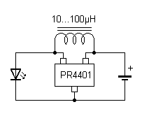
LED-Treiber PR4401 SOT23


Here you can see what the results of the experiment led to.
The circuit presented to your attention was used to power an LED flashlight, recharge a mobile phone from two metal hydrite batteries, and when creating a microcontroller device, a radio microphone. In each case, the operation of the circuit was flawless. The list where you can use the MAX1674 can go on for a long time.
The easiest way to get a more or less stable current through an LED is to connect it to an unstabilized power supply circuit through a resistor. It must be taken into account that the supply voltage must be at least twice the operating voltage of the LED. The current through the LED is calculated by the formula:
I led = (Umax. power supply - U working diode) : R1
This scheme is extremely simple and in many cases is justified, but it should be used where there is no need to save electricity and there are no high requirements for reliability.
More stable circuits based on linear stabilizers:
It is better to choose adjustable or fixed voltage stabilizers as stabilizers, but it should be as close as possible to the voltage on the LED or a chain of series-connected LEDs.
Stabilizers like LM 317 are very suitable.
German text:
iel war es, mit nur einer NiCd-Zelle (AAA, 250mAh) eine der neuen ultrahellen LEDs mit 5600mCd zu betreiben. Diese LEDs benötigen 3.6V/20mA. Ich habe Ihre Schaltung zunächst unverändert übernommen, als Induktivität hatte ich allerdings nur eine mit 1,4mH zur Hand. Die Schaltung lief auf Anhieb! Allerdings ließ die Leuchtstärke doch noch zu wünschen übrig. Mehr zufällig stellte ich fest, dass die LED extrem heller wurde, wenn ich ein Spannungsmessgerät parallel zur LED schaltete!??? Tatsächlich waren es nur die Messschnüre, bzw. deren Kapazität, die den Effekt bewirkten. Mit einem Oszilloskop konnte ich dann feststellen, dass in dem Moment die Frequenz stark anstieg. Hm, also habe ich den 100nF-Kondensator gegen einen 4.7nF Typ ausgetauscht und schon war die Helligkeit wie gewünscht. Anschließend habe ich dann nur noch durch Ausprobieren die beste Spule aus meiner Sammlung gesucht... Das beste Ergebnis hatte ich mit einem alten Sperrkreis für den 19KHz Pilotton (UKW), aus dem ich die Kreiskapazität entfernt habe. Und hier ist sie nun, die Mini-Taschenlampe:
Sources:
http://pro-radio.ru/
http://radiokot.ru/
During the time of my passion for tourism, I purchased a Duracell flashlight with a powerful krypton lamp on two large D-size batteries (in the Soviet version, type 373). The light was excellent, but it drained the batteries in 3-4 hours.
In addition, trouble happened twice - the batteries leaked and electrolyte flooded everything inside the flashlight. The contacts were oxidized, covered with rust, and even after cleaning and installing new batteries, the flashlight no longer inspired confidence, much less the batteries. It was a pity to throw it away, but not having the opportunity to use it gave me the idea to convert the flashlight to the now fashionable lithium battery and LED. For six months, I had a Sanyo 18650 lithium battery with a capacity of 2600 mAh lying in the bins, and from my Chinese comrades I ordered this LED (supposedly Cree XML T6 U2) with an operating voltage of 3-3.6 V, a current of 0.3-3 A (again, supposedly with a power of 10 W), a luminous flux of 1000-1155 lumens, a color temperature of 5500-6500 K and a dispersion angle of 170 degrees.

Since I already had experience converting flashlights to be powered by lithium batteries (and), I decided to go the same way: use a well-proven combination: 18650 battery and TP4056 charge controller. There was only one problem left to solve - which driver to use for the LED? You can't get away with a simple current-limiting resistor - the power of the LED may not be 10 Watts, as the Chinese comrades claim, but still. While studying material on “driver development for high-power LEDs,” I came across a very interesting, and, as it turned out, frequently used AMC7135 microcircuit. Based on this microcircuit, the Chinese have long and successfully filled the planet with their lanterns). Schematic diagram of power supply for a high-power LED based on AMC7135.

As you can see, power is allowed in the range of 2.7...6 V, and this is a fairly wide range of power sources, including lithium batteries. The chip's job is to limit the current flowing through the LED to 350 mA.
According to the chip manufacturer, capacitor Co should be used if:
- the length of the conductor between AMC7135 and the LED is more than 3 cm;
- the length of the conductor between the LED and the power source is more than 10 cm;
- The LED and the chip are not installed on the same board.
In reality, flashlight manufacturers often neglect these conditions and exclude capacitors from the circuit. But as the experiment showed, it was in vain, about which a little later. Additional advantages of the AMC7135 type IC include the presence of built-in protection in the event of a break, LED short circuit and an operating temperature range of -4O...85°C. Detailed documentation for the AMC7135 chip can be found here.
Electrical circuit of the flashlight
Another important and extremely useful feature of this chip is that they can be installed in parallel to increase the current flowing through the LED. As a result, the following scheme was born:

Based on it, the current flowing through the LED will be 1050 mA, which, in my opinion, is more than enough for a not at all tactical, but a utility flashlight. Then I started installing everything into a single system. Using a Dremel, I removed the battery guides and contact bars from the flashlight body:


I also removed the mounting socket for the krypton lamp with a Dremel and formed a platform for the LED

Since a powerful LED generates a lot of heat during operation, I decided to use a heat sink removed from the motherboard to dissipate it.


As planned, the LED, heat sink and head part of the flashlight with reflector will form one whole and, when screwed onto the flashlight body, should not cling to anything. To do this, I cut off the edges of the heat sink, drilled holes for the wires and glued the LED to the heat sink with hot glue.


