20.06.2020
Springs and other elastic elements. Springs and elastic elements springs and elastic elements. First, general concepts
 SPRINGS AND ELASTIC ELEMENTS n n n 1. general characteristics springs Springs are widely used in structures as vibration-isolating, shock-absorbing, return-feeding, tensioning, dynamometer and other devices. Types of springs. Based on the type of external load perceived, springs are divided into tension, compression, torsion and bending springs.

 SPRINGS AND ELASTIC ELEMENTS n n coiled springs (cylindrical - tension, Fig. 1 a, compression, Fig. 1 b; torsion, Fig. 1 c, shaped compression, Fig. 1 d-f), special springs (disc and ring, Fig. 2 a and b, - compression; springs and springs, Fig. 2 c, - bending; spiral, Fig. 2 d - torsion, etc.) The most common are twisted cylindrical springs made of round wire.
 SPRINGS AND ELASTIC ELEMENTS n Tension springs (see Fig. 1 a) are wound, as a rule, without gaps between the turns, and in most cases - with an initial tension (pressure) between the turns, partially compensating for the external load. The tension is usually (0.25 - 0.3) Fpr (Fnp is the maximum tensile force at which the elastic properties of the spring material are completely exhausted).
 SPRINGS AND ELASTIC ELEMENTS n n To transmit external load, such springs are equipped with hooks. For example, for springs of small diameter (3-4 mm), the hooks are made in the form of bent last turns (Fig. 3 a-c). However, such hooks reduce the resistance of fatigue springs due to the high stress concentration in the bend areas. For critical springs with a diameter of over 4 mm, embedded hooks are often used (Fig. 3 d-e), although they are less technologically advanced.
 SPRINGS AND ELASTIC ELEMENTS n n n Compression springs (see Fig. 1 b) are wound with a gap between the turns, which should be 10-20% greater than the axial elastic movements of each turn at the greatest external load. The supporting planes of the springs are obtained by pressing the last turns against the adjacent ones and grinding them perpendicular to the axis. Long springs may become unstable (bulge) under load. To prevent bulging, such springs are usually placed on special mandrels (Fig. 4 a) or in glasses (Fig. 4 b).


 SPRINGS AND ELASTIC ELEMENTS n n n The alignment of the springs with the mating parts is achieved by installing support coils in special plates, bores in the body, grooves (see Fig. 4 c). Torsion springs (see Fig. 1c) are usually wound with a small angle of elevation and small gaps between the coils (0.5 mm). They perceive external load with the help of hooks formed by bending the end turns.
 SPRINGS AND ELASTIC ELEMENTS n n Basic parameters of coil springs. Springs are characterized by the following main parameters (see Fig. 1 b): wire diameter d or cross-sectional dimensions; average diameter Do, index c = Do/d; number n of working turns; length Ho of the working part; step t = Ho/n turns, angle =arctg rise of turns. The last three parameters are considered in unloaded and loaded states.
 SPRINGS AND ELASTIC ELEMENTS n n The spring index characterizes the curvature of the coil. Springs with index 3 are not recommended for use due to the high stress concentration in the coils. Typically, the spring index is selected depending on the wire diameter as follows: for d 2.5 mm, d = 3--5; 6-12 mm respectively c = 5-12; 4-10; 4-9.
 SPRINGS AND ELASTIC ELEMENTS n n Materials. Twisted springs are made by cold or hot coiling, followed by finishing of the ends, heat treatment and control. The main materials for springs are high-strength special spring wire of classes 1, II and III with a diameter of 0, 2-5 mm, as well as steel: high-carbon 65, 70; manganese 65 G; silicon 60 C 2 A, chrome vanadium 50 CFA, etc.
 SPRINGS AND ELASTIC ELEMENTS n n Springs intended for operation in a chemically active environment are made of non-ferrous alloys. To protect the surfaces of the coils from oxidation of the spring responsible appointment varnished or oiled, and springs for special purposes are oxidized, and also coated with zinc or cadmium
 SPRINGS AND ELASTIC ELEMENTS n n 2. Calculation and design of twisted cylindrical springs Stresses in sections and displacement of coils. Under the action of an axial force F (Fig. 5 a), a resultant internal force F appears in the cross section of the spring coil, parallel to the spring axis, and a moment T = F D 0/2, the plane of which coincides with the plane of the pair of forces F. The normal cross section of the coil is inclined to moment plane at an angle.

 SPRINGS AND ELASTIC ELEMENTS n n Projecting force factors in the cross section of a loaded spring onto the x, y and z axes (Fig. 5, b), associated with the normal section of the coil, force F and moment T, we obtain Fx = F cos ; Fn = F sin (1) T = Mz = 0.5 F D 0 cos ; Mx = 0.5 F D 0 sin ;
 SPRINGS AND ELASTIC ELEMENTS n n n The angle of elevation of the turns is small (usually 12). Therefore, we can assume that the cross section of the spring works for torsion, neglecting other force factors. In the coil section, the maximum tangential stress (2) where Wk is the moment of resistance to torsion of the coil section
 SPRINGS AND ELASTIC ELEMENTS n Taking into account the curvature of the coils and relation (2), we write in the form equality (1), (3) n where F is the external load (tensile or compressive); D 0 - average spring diameter; k - coefficient taking into account the curvature of the turns and the shape of the section (amendment to the formula for torsion of a straight beam); k is the permissible punitive stress during torsion.
 SPRINGS AND ELASTIC ELEMENTS n The value of the coefficient k for springs made of round wire with index c 4 can be calculated using the formula
 SPRINGS AND ELASTIC ELEMENTS n n Taking into account that for a wire of round cross-section Wk = d 3 / 16, then (4) A spring with an elevation angle of 12 has axial displacement n F, (5)
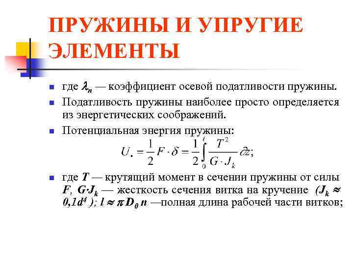 SPRINGS AND ELASTIC ELEMENTS n n where n is the coefficient of axial compliance of the spring. The compliance of a spring is most simply determined from energy considerations. Potential energy of the spring: where T is the torque in the spring cross-section due to force F, G Jk is the torsional rigidity of the coil section (Jk 0, 1 d 4); l D 0 n - total length of the working part of the turns;

 SPRINGS AND ELASTIC ELEMENTS n and coefficient of axial compliance of the spring (7) n where is the axial compliance of one turn (settlement in millimeters under the action of force F = 1 N),
 SPRINGS AND ELASTIC ELEMENTS n determined by formula (8) n where G = E/ 0.384 E is the shear modulus (E is the elastic modulus of the spring material).
 SPRINGS AND ELASTIC ELEMENTS n From formula (7) it follows that the spring compliance coefficient increases with an increase in the number of turns (spring length), its index (outer diameter) and a decrease in the shear modulus of the material.
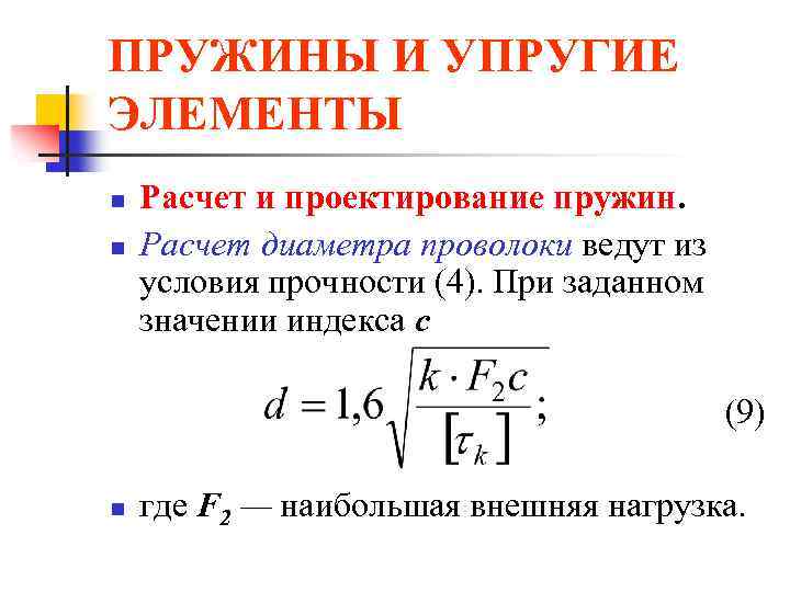 SPRINGS AND ELASTIC ELEMENTS n n Calculation and design of springs. The wire diameter is calculated from the strength condition (4). For a given index value c (9) n where F 2 is the greatest external load.
 SPRINGS AND ELASTIC ELEMENTS n The permissible stresses [k] for springs made of steels 60 C 2, 60 C 2 N 2 A and 50 HFA are: 750 MPa - under the action of static or slowly changing variable loads, as well as for springs of non-critical purposes; 400 MPa - for critical dynamically loaded springs. For dynamically loaded bronze responsible springs [k] are assigned (0.2-0.3) in; for non-responsible bronze springs - (0.4-0.6) c.
 SPRINGS AND ELASTIC ELEMENTS n n The required number of working turns is determined from relation (5) according to the given elastic movement (stroke) of the spring. If the compression spring is installed with pre-tensioning (load) F 1, then (10) Depending on the purpose of the spring, force F 1 = (0.1-0.5) F 2. By changing the value of F 1, the working draft of the spring can be adjusted. The number of turns is rounded to half a turn for n 20 and to one turn for n > 20.
 SPRINGS AND ELASTIC ELEMENTS n Total number of turns n n H 0 = H 3 + n (t - d), (12) where H 3 = (n 1 - 0. 5) d is the length of the spring, compressed until adjacent working turns touch; t - spring pitch. n n n 1 = n + (l, 5 -2, 0). (11) An additional 1.5-2 turns are used for compression to create supporting surfaces for the spring. In Fig. Figure 6 shows the relationship between load and compression spring upset. Total length of unloaded spring n

 SPRINGS AND ELASTIC ELEMENTS n n The total number of turns is reduced by 0.5 due to the grinding of each end of the spring by 0.25 d to form a flat bearing end. Maximum draft springs, i.e. the movement of the end of the spring until the coils are in full contact (see Fig. 6), is determined by the formula
 SPRINGS AND ELASTIC ELEMENTS n n n The spring pitch is determined depending on the value 3 from the following approximate ratio: The length of wire required for the manufacture of the spring where = 6 - 9° is the angle of elevation of the turns of the unloaded spring.
 SPRINGS AND ELASTIC ELEMENTS n n To prevent the spring from buckling due to loss of stability, its flexibility H 0/D 0 should be less than 2.5. If, for design reasons, this limitation is not met, then the springs, as indicated above, should be placed on mandrels or mounted in sleeves .
 SPRINGS AND ELASTIC ELEMENTS n n n The installation length of the spring, i.e. the length of the spring after tightening it with force F 1 (see Fig. 6), is determined by the formula H 1 = H 0 - 1 = H 0 - n F 1 under the action of the greatest external load, spring length H 2 =H 0 - 1 = H 0 - n F 2 and the smallest spring length will be at force F 3 corresponding to length H 3 = H 0 - 3
 SPRINGS AND ELASTIC ELEMENTS n The angle of inclination of the straight line F = f() to the abscissa axis (see Fig. 6) is determined from the formula
 SPRINGS AND ELASTIC ELEMENTS n For heavy loads and cramped dimensions, use Compound compression springs (see Fig. 4, c) - a set of several (usually two) concentrically located springs that simultaneously perceive external load. To prevent strong twisting of the end supports and distortions, the coaxial springs are wound in opposite directions (left and right). The supports are designed to ensure mutual alignment of the springs.
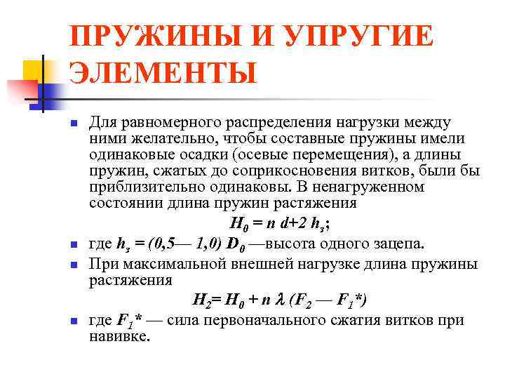 SPRINGS AND ELASTIC ELEMENTS n n To evenly distribute the load between them, it is desirable that the composite springs have the same settlements (axial movements), and the lengths of the springs compressed until the coils touch each other are approximately the same. In the unloaded state, the length of the tension springs Н 0 = n d+2 hз; where hз = (0, 5- 1, 0) D 0 is the height of one hook. At maximum external load, the length of the tension spring H 2 = H 0 + n (F 2 - F 1 *) where F 1 * is the force of the initial compression of the turns during winding.
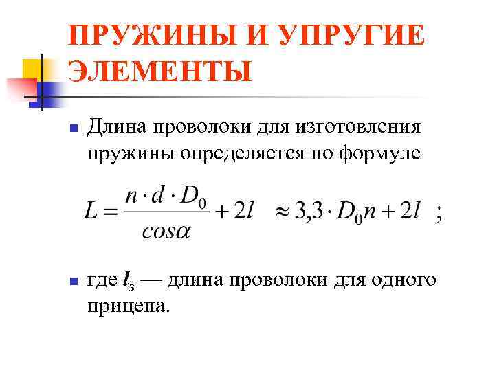 SPRINGS AND ELASTIC ELEMENTS n n The length of the wire for making a spring is determined by the formula where lз is the length of the wire for one trailer.
 SPRINGS AND ELASTIC ELEMENTS n Common springs are those in which, instead of wire, a cable twisted from two to six wires of small diameter (d = 0.8 - 2.0 mm) is used - stranded springs. In terms of design, such springs are equivalent to concentric springs. Due to their high damping capacity (due to friction between the strands) and compliance, stranded springs work well in shock absorbers and similar devices. When exposed to variable loads, stranded springs quickly fail due to wear of the strands.
 SPRINGS AND ELASTIC ELEMENTS n In structures operating under conditions of vibration and shock loads, shaped springs are sometimes used (see Fig. 1, d-f) with a nonlinear relationship between external force and elastic movement of the spring.
 SPRINGS AND ELASTIC ELEMENTS n n Safety margins. When exposed to static loads, springs may fail due to plastic deformations in the coils. According to plastic deformations, the safety factor is where max is the highest tangential stress in the spring coil, calculated by formula (3), at F=F 1.
 SPRINGS AND ELASTIC ELEMENTS n Springs that operate for a long time under variable loads must be designed for fatigue resistance. Springs are characterized by asymmetric loading, in which the forces vary from F 1 to F 2 (see Fig. 6). At the same time, in the cross sections of the voltage turns
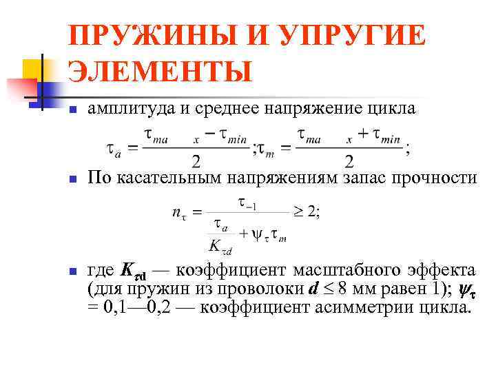 SPRINGS AND ELASTIC ELEMENTS n amplitude and average cycle stress n For tangential stresses, safety factor n where K d is the scale effect coefficient (for springs made of wire d 8 mm is equal to 1); = 0, 1 - 0, 2 - cycle asymmetry coefficient.
 SPRINGS AND ELASTIC ELEMENTS n n Fatigue limit - 1 wire with variable torsion in a symmetrical cycle: 300-350 MPa - for steels 65, 70, 55 GS, 65 G; 400-450 MPa - for steels 55 C 2, 60 C 2 A; 500-550 MPa - for steels 60 C 2 HFA, etc. When determining the safety factor, the effective stress concentration coefficient K = 1 is taken. The stress concentration is taken into account by the coefficient k in the formulas for stresses.
 SPRINGS AND ELASTIC ELEMENTS n In the case of resonant oscillations of springs (for example, valve springs), an increase in the variable component of the cycle may occur while m remains unchanged. In this case, the safety margin is alternating voltages
 SPRINGS AND ELASTIC ELEMENTS n To increase fatigue resistance (by 20-50%), the springs are strengthened by shot peening, which creates compressive residual stresses in the surface layers of the coils. To process springs, balls with a diameter of 0.5-1.0 mm are used. It is more effective to treat springs with balls of small diameters at high flight speeds.
 SPRINGS AND ELASTIC ELEMENTS n n Calculation for impact load. In a number of structures (shock absorbers, etc.), springs operate under shock loads applied almost instantly (at high speed) with known impact energy. The individual coils of the spring receive significant speed and can collide dangerously. The calculation of real systems for impact loading is associated with significant difficulties (taking into account contact, elastic and plastic deformations, wave processes, etc.); Therefore, for the engineering application we will limit ourselves to the energy calculation method.
 SPRINGS AND ELASTIC ELEMENTS n n n The main task of shock load calculation is to determine the dynamic settlement (axial movement) and static load equivalent to the impact on a spring with known sizes. Let us consider the impact of a rod of mass m on a spring shock absorber (Fig. 7). If we neglect the deformation of the piston and assume that after an impact, elastic deformations instantly cover the entire spring, we can write the energy balance equation in the form where Fd is the gravity force of the rod; K is the kinetic energy of the system after the collision,
 SPRINGS AND ELASTIC ELEMENTS n determined by formula (13) n where v 0 is the speed of movement of the piston; - coefficient of reduction of the spring mass to the point of impact
 SPRINGS AND ELASTIC ELEMENTS n n n If we assume that the speed of movement of the coils of the spring changes linearly along its length, then = 1/3. The second term on the left side of equation (13) expresses the work of the piston after a collision during dynamic upsetting of the spring. The right side of equation (13) is the potential energy of deformation of the spring (with compliance m), which can be returned by gradually unloading the deformed spring.


 SPRINGS AND ELASTIC ELEMENTS With instantaneous application of load v 0 = 0; d = 2 tbsp. A static load, equivalent in effect to impact, can. calculated from the relation n n
 SPRINGS AND ELASTIC ELEMENTS n n Rubber elastic elements used in the design of elastic couplings, vibration and noise insulating supports and other devices for obtaining large movements. Such elements usually transmit the load through metal parts (plates, tubes, etc.).
 SPRINGS AND ELASTIC ELEMENTS n Advantages of rubber elastic elements: electrical insulating ability; high damping capacity (energy dissipation in rubber reaches 30-80%); the ability to accumulate more energy per unit mass than spring steel (up to 10 times). In table Figure 1 shows calculation diagrams and formulas for approximate determination of stresses and displacements for rubber elastic elements.
 SPRINGS AND ELASTIC ELEMENTS n n Material of elements - technical rubber with tensile strength (8 MPa; shear modulus G = 500-900 MPa. V last years Pneumoelastic elastic elements are becoming widespread.
Metallic and non-metallic elements are used as elastic devices in the suspensions of modern cars. The most common metal devices are springs, leaf springs and torsion bars.
Car suspension spring with variable stiffness
Most widely (especially in pendants passenger cars) apply coil springs, made from a steel elastic rod of circular cross-section.
When the spring is compressed along the vertical axis, its coils come closer together and twist. If the spring has a cylindrical shape, then when it is deformed, the distance between the coils remains constant and the spring has a linear characteristic. This means that the deformation of a coil spring is always directly proportional to the applied force, and the spring has a constant stiffness. If you make a twisted spring from a rod of variable cross-section or give the spring a certain shape (in the form of a barrel or cocoon), then such an elastic element will have variable stiffness. When such a spring is compressed, the less rigid coils will initially come closer together, and after they touch, the more rigid coils will begin to work. Springs of variable stiffness are widely used in suspensions of modern passenger cars.
The advantages of springs used as elastic elements of suspensions include their low mass and the ability to ensure high smoothness of the vehicle. At the same time, the spring cannot transmit forces in the transverse plane and its use requires a complex guide device in the suspension.

Rear leaf spring suspension:
1 - spring eye;
2 - rubber bushing;
3 - bracket;
4 - bushing;
5 - bolt;
6 - washers;
7 - finger;
8 - rubber bushings;
9 - spring washer;
10 - nut;
11 - bracket;
12 - rubber bushing;
13 - bushing;
14 - earring plate;
15 - bolt;
16 - stabilizer bar;
17 - root leaf;
18 - spring leaves;
19 - rubber compression stroke buffer;
20 - stepladders;
21 - overlay;
22 - rear axle beam;
23 - shock absorber;
24 - clamp;
25 - frame spar;
26 - stabilizer bracket;
27 - stabilizer earring
Leaf spring served as an elastic suspension element on horse-drawn carriages and the first cars, but it continues to be used today, although mainly on trucks. A typical leaf spring consists of a series of sheets of varying lengths fastened together, made of spring steel. A leaf spring is usually shaped like a semi-ellipse.

Methods of fastening springs:
a - with twisted ears;
b - on rubber cushions;
c - with an overhead eyelet and a sliding support
The sheets that make up the spring have different lengths and curvatures. How shorter length sheet, the greater its curvature should be, which is necessary for a tighter mutual fit of the sheets in the assembled spring. With this design, the load on the longest (main) leaf of the spring is reduced. The spring leaves are fastened together with a center bolt and clamps. With the help of the main leaf, the spring is hinged at both ends to the body or frame and can transmit forces from the wheels of the car to the frame or body. The shape of the ends of the main sheet is determined by the method of attaching it to the frame (body) and the need to compensate for changes in the length of the sheet. One end of the spring must be able to pivot while the other ends rotate and move.
When a spring is deformed, its leaves bend and change their length. In this case, the sheets rub against each other, and therefore they require lubrication, and special anti-friction gaskets are installed between the sheets of the springs of passenger cars. At the same time, the presence of friction in the spring makes it possible to dampen body vibrations and, in some cases, makes it possible to do without the use of shock absorbers in the suspension. The spring suspension has simple design, But large mass, which determines its greatest distribution in the suspensions of trucks and some cross-country passenger cars. To reduce the mass of spring suspensions and improve smoothness, they are sometimes used few-leaved And single-leaf springs with sheet of variable length section. Quite rarely, springs made of reinforced plastic are used in suspensions.

Torsion bar suspension. The rear suspension of the Peugeot 206 uses two torsion bars connected to trailing arms. The suspension guide uses tubular arms mounted at an angle to the longitudinal axis of the vehicle
Torsion- a metal elastic element that works for torsion. Typically, a torsion bar is a solid metal rod of round cross-section with thickenings at the ends on which slots are cut. There are suspensions in which torsion bars are made of a set of plates or rods (ZAZ cars). One end of the torsion bar is attached to the body (frame), and the other to the guide device. When the wheels move, the torsion bars twist, providing an elastic connection between the wheel and the body. Depending on the suspension design, torsion bars can be located either along the longitudinal axis of the car (usually under the floor) or transversely. Torsion bar suspensions are compact and lightweight and make it possible to adjust the suspension by pre-twisting the torsion bars.
Non-metallic elastic elements of suspensions are divided into rubber, pneumatic And hydropneumatic.
Rubber elastic elements are present in almost all suspension designs, but not as main ones, but as additional ones, used to limit the movement of wheels up and down. The use of additional rubber stops (buffers, bumpers) limits the deformation of the main elastic elements of the suspension, increasing its rigidity during large movements and preventing metal-to-metal impacts. IN Lately rubber elements are increasingly being replaced by devices made of synthetic materials (polyurethane).

Elastic elements of air suspensions:
a - sleeve type;
b- double cylinders
IN pneumatic elastic elements elastic properties are used compressed air. The elastic element is a cylinder made of reinforced rubber, into which air is supplied under pressure from a special compressor. The shape of air cylinders can be different. Sleeve-type cylinders (a) and double (two-section) cylinders (b) have become widespread.
The advantages of pneumatic elastic suspension elements include the high smoothness of the vehicle's ride, low weight and the ability to maintain a constant level of the body floor, regardless of the vehicle's load. Suspensions with pneumatic elastic elements are used on buses, trucks and cars. The constant level of the floor of the cargo platform ensures the convenience of loading and unloading a truck, and for cars and buses - convenience when boarding and disembarking passengers. To obtain compressed air, buses and trucks with a pneumatic braking system use standard compressors driven by the engine, and special compressors are installed on passenger cars, usually with an electric drive (Range Rover, Mercedes, Audi).

Air suspension. On new Mercedes E-class cars, pneumatic elastic elements began to be used instead of springs
The use of pneumatic elastic elements requires the use of a complex guide element and shock absorbers in the suspension. The suspensions with pneumatic elastic elements of some modern passenger cars have complex electronic control, which ensures not only a constant body level, but also an automatic change in the rigidity of individual air cylinders when cornering and when braking, to reduce body roll and dive, which generally increases driving comfort and safety.

Hydropneumatic elastic element:
1 - compressed gas;
2 - body;
3 - liquid;
4 - to the pump;
5 - to the shock absorber strut
The hydropneumatic elastic element is a special chamber divided into two cavities by an elastic membrane or piston.
One of the chamber cavities is filled with compressed gas (usually nitrogen), and the other with liquid (special oil). Elastic properties are provided by compressed gas, since the liquid is practically incompressible. The movement of the wheel causes the movement of a piston located in a cylinder filled with liquid. As the wheel moves upward, the piston displaces liquid from the cylinder, which enters the chamber and acts on the separating membrane, which moves and compresses the gas. For supporting required pressure The system uses a hydraulic pump and a hydraulic accumulator. By changing the pressure of the liquid entering under the membrane of the elastic element, you can change the gas pressure and the stiffness of the suspension. When the body oscillates, the fluid passes through the valve system and experiences resistance. Hydraulic friction provides the damping properties of the suspension. Hydropneumatic suspensions provide a highly smooth ride, the ability to adjust the position of the body and effective damping of vibrations. The main disadvantages of such a suspension include its complexity and high cost.
Recently, long-known in technology, but little used, multi-strand springs have again begun to be used, consisting of several wires (strands) twisted into ropes (Fig. 902, I-V), from which springs are wound (compression, tension, torsion). The ends of the rope are scalded to prevent the strands from unraveling. The lay angle δ (see Fig. 902, I) is usually made equal to 20-30°.
The direction of twist of the cable is chosen in such a way that the cable twists rather than unwinds during elastic deformation of the spring. Compression springs with right-handed turns are made from left-handed ropes, and vice versa. For tension springs, the direction of twist and the inclination of the coils must coincide. In torsion springs, the direction of the twist does not matter.
Lay density, lay pitch and lay technology influence big influence on the elastic characteristics of stranded springs. After laying the rope, elastic recoil occurs and the strands move away from each other. Winding the springs, in turn, changes mutual arrangement lived turns.

In the free state of the spring, there is almost always a gap between the cores. In the initial stages of loading, the spring cores act as separate wires; its characteristic (Fig. 903) has a flat appearance.
With a further increase in loads, the cable twists, the strands close and begin to work as one; the spring stiffness increases. For this reason, the characteristics of stranded springs have a turning point (a) corresponding to the beginning of the closure of the coils.

The advantage of stranded springs is due to the following. The use of several thin wires instead of one massive one allows you to increase the design stresses due to the inherent increased strength of thin wires. A coil composed of small-diameter strands has greater compliance than an equivalent solid coil, partly due to the increased permissible stresses, but mainly due to the higher value of the index c = D/d for each individual strand, which dramatically affects the stiffness.
The flat characteristic of stranded springs can be useful in a number of cases when it is necessary to obtain large elastic deformations within limited axial and radial dimensions.
Other distinctive feature stranded springs - increased damping capacity due to friction between coils during elastic deformation. Therefore, such springs can be used to dissipate energy under shock-like loads, to dampen vibrations that occur under such loads; they also contribute to the self-damping of the resonant oscillations of the spring coils.
However, increased friction causes wear of the coils, accompanied by a decrease in the fatigue resistance of the spring.
When comparatively assessing the flexibility of stranded springs and single-wire springs, a mistake is often made by comparing springs with the same cross-sectional area (total for stranded) coils.
At the same time, they do not take into account the fact that the load capacity of stranded springs with other equal conditions less than single-wire springs, and it decreases with increasing number of wires.
The assessment must be based on the condition of equal load capacity. Only in this case it is correct with a different number of cores. In this assessment, the benefits of stranded springs appear more modest than might be expected.
Let us compare the compliance of stranded springs and a single-wire spring with the same average diameter, number of turns, force (load) P and safety factor.
As a first approximation, we will consider a multi-core spring as a series of parallel operating springs with coils of small cross-section.
The diameter d" of the strand of a stranded spring under these conditions is related to the diameter d of the solid wire by the relation

where n is the number of cores; [τ] and [τ"] - permissible stresses shift; k and k" are the spring shape coefficients (their index).
Due to the closeness of the values  can be written to one

Mass ratio of compared springs

or with the substitution of the value d"/d from equation (418)
The values of the ratios d"/d and m"/m depending on the number of cores are given below.
As you can see, the decrease in the wire diameter of multi-strand springs is not at all so great as to give a significant gain in strength even in the region of small values of d and d" (by the way, this circumstance justifies the assumption made above that the factor is close to unity.
Ratio of deformation λ" of a stranded spring to deformation λ of a spring made of solid wire
![]()
Substituting d"/d from equation (417) into this expression, we obtain
![]()
The value of [τ"]/[τ], as indicated above, is close to unity. Therefore
![]()
The values of λ"/λ calculated from this expression for different numbers of cores n are given below (in the determination, the initial value k = 6 was taken for k).
As can be seen, with the initial assumption of equality of load, the transition to multi-strand springs ensures real values number of veins, the gain in compliance is 35-125%.
In Fig. 904 shows a summary diagram of the change in factors d"/d; λ"/λ and m"/m for equally loaded and equal-strength stranded springs depending on the number of strands.

Along with the increase in mass as the number of cores increases, an increase in the cross-sectional diameter of the turns should be taken into account. For the number of cores in the range n = 2-7, the cross-sectional diameter of the turns is on average 60% larger than the diameter of the equivalent whole wire. This leads to the fact that in order to maintain clearance between the coils it is necessary to increase the pitch and total length of the springs.
The gain in compliance provided by multi-strand springs can be obtained in a single-wire spring. To do this, the diameter D of the spring is simultaneously increased; reduce the diameter d of the wire; increase the stress level (i.e. use high-quality steel). Ultimately, a uniform single-wire spring will have less weight, smaller dimensions, and will be significantly cheaper than a stranded spring due to the complexity of manufacturing stranded springs. To this we can add the following disadvantages of stranded springs:
1) the impossibility (for compression springs) of correct threading of the ends (by grinding the ends of the spring), ensuring central application of the load; there is always some eccentricity of the load, causing additional bending of the spring;
2) complexity of manufacturing;
3) dispersion of characteristics for technological reasons; difficulty in obtaining stable and reproducible results;
4) wear of the cores as a result of friction between the turns, which occurs during repeated deformations of the springs and causes a sharp drop in the fatigue resistance of the springs. The last drawback excludes the use of multi-strand springs under long-term cyclic loading.
Stranded springs are suitable for static loading and periodic dynamic loading with a limited number of cycles.
In instrument making, springs of various geometric shapes are widely used. They are flat, curved, spiral, screw.
6.1. Flat springs
6.1.1 Applications and designs of flat springs
A flat spring is a plate that bends and is made of an elastic material. During manufacturing, it can be given a shape that is convenient for placement in the device body, while it may take up little space. A flat spring can be made from almost any spring material.
Flat springs are widely used in various electrical contact devices. The most widespread is one of the simplest forms of a flat spring in the form of a straight rod clamped at one end (Fig. 6.1, a).
A - contact group of the electromagnetic relay; b - changeover contact;
V - sliding contact springs
Rice. 6.1 Contact springs:
Using a flat spring, a reversible elastic microswitch system can be made, providing sufficient high speed triggering (Fig. 6.1, b).
Flat springs are also used in electrical contact devices as sliding contacts (Fig. 6.1, c).
Elastic supports and guides made of flat springs have no friction or backlash, do not require lubrication, and are not susceptible to contamination. The disadvantage of elastic supports and guides is the limited linear and angular movements.
Significant angular movements are allowed by a spiral-shaped measuring spring - a hair. Hairs are widely used in many indicating electrical measuring instruments and intended for selecting backlashes in the transmission mechanism of the device. The twist angle of the hair is limited both for reasons of strength and due to the loss of stability of the flat shape of the bend of the hair at sufficiently large twist angles.
The mainsprings have a spiral shape and act as a motor.

Rice. 6.2 Methods for securing flat springs
6.1.2 Calculation of flat and spiral springs
Flat straight and curved springs are a plate of a given shape (straight or curved), which elastically bends under the influence of external loads, i.e., bends. These springs are usually used in cases where the force acts on the spring within a small stroke.
Depending on the methods of fastening and places where loads are applied, flat springs are distinguished:
- working as cantilever beams with a concentrated load at the free end (Fig. 6.2 a);
- working like beams, freely lying on two supports with a concentrated load (Fig. 6.2 b);
- working like beams, one end of which is fixed, and the other freely lies on a support with a concentrated load (Fig. 6.2 c);
- working like beams, one end of which is hinged, and the other freely lies on a support with a concentrated load (Fig. 6.2 d);
- which are round plates fixed at the edges and loaded in the middle (membranes) (Fig. 6.2 d).
A)  c) d)
c) d)
When designing flat leaf springs, you should, if possible, choose the simplest shapes for them to facilitate their calculation. Flat springs are calculated using the formulas
Spring deflection from load in, m |
||
Spring thickness in m |
||
Spring width in m |
||
Set according to operating conditions |
||
RR |
Selected by |
|
Working deflection of the spring in m |
constructive |
|
Working length of spring in m |
considerations |
Coil springs are usually placed in a drum to give the spring certain external dimensions.
ELASTIC ELEMENTS. SPRINGS
Wheel pairs of cars are connected to the bogie frame and the car body through a system of elastic elements and vibration dampers, called spring suspension. Spring suspension, due to elastic elements, softens shocks and impacts transmitted by the wheels to the body, and also, due to the work of dampers, dampens vibrations that occur when the car moves. In addition (in some cases), springs and springs transmit guiding forces from the wheels to the car bogie frame.
When a wheel pair passes any unevenness on the track (joints, crosses, etc.), dynamic loads arise, including shock. The appearance of dynamic loads is also facilitated by defects in the wheelset - local defects of the rolling surfaces, eccentricity of the wheel fit on the axle, imbalance of the wheelset, etc. In the absence of spring suspension, the body would rigidly perceive all dynamic influences and experience high accelerations.
Elastic elements located between the wheel pairs and the body, under the influence of dynamic force from the wheel pair, are deformed and perform oscillatory movements together with the body, and the period of such oscillations is many times longer than the period of change of the disturbing force. As a result, accelerations and forces perceived by the body are reduced.
Let us consider the softening effect of spring suspension when transmitting shocks to the body using the example of the movement of a car along a rail track. When a car wheel rolls along a rail track, due to the unevenness of the rail and defects in the rolling surface of the wheel, the car body, when connected without springs to the wheel pairs, will copy the trajectory of the wheel (Fig. A). The trajectory of the car body (line a1-b1-c1) coincides with the unevenness of the track ( line a-b-c). If there is a spring suspension, vertical shocks (Fig. b) are transmitted to the body through elastic elements, which, softening and partially absorbing shocks, ensure a calmer and smoother ride of the car, protect the rolling stock and track from premature wear and damage. The trajectory of the body can be depicted by the line a1-b2-c2, which has a flatter appearance compared to the line a in c. As can be seen from Fig. b, the period of vibration of the body on the springs is many times greater than the period of change of the disturbing force. As a result, accelerations and forces perceived by the body are reduced.
Springs are widely used in railcar construction, in bogies of freight and passenger cars, and in shock-traction devices. There are screw and spiral springs. Helical springs are made by curling steel rods of round, square or rectangular cross-section. Coil springs are cylindrical and conical in shape.

Types of coil springs
a - cylindrical with a rectangular cross-section of the rod; b - cylindrical with a round cross-section of the rod; c - conical with a round cross-section of the rod; g - conical with a rectangular cross-section of the rod
In the spring suspension of modern cars, cylindrical springs are most widespread. They are easy to manufacture, reliable in operation and well absorb vertical and horizontal shocks and impacts. However, they cannot dampen vibrations of the car's sprung masses and are therefore used only in combination with vibration dampers.
Springs are manufactured in accordance with GOST 14959. The supporting surfaces of the springs are made flat and perpendicular to the axis. To do this, the ends of the spring blank are pulled back to 1/3 the length of the coil circumference. As a result, a smooth transition from round to rectangular cross-section is achieved. The height of the drawn end of the spring should be no more than 1/3 of the rod diameter d, and the width should be no less than 0.7d.
The characteristics of a cylindrical spring are: diameter of the rod d, average diameter of the spring D height of the spring in the free Нсв and compressed Нсж states, the number of working turns nр and index m. The spring index is the ratio of the average diameter of the spring to the diameter of the rod, i.e. t = D/d.

Cylindrical spring and its parameters
Material for springs and leaf springs
The material for springs and springs must have high static, dynamic, impact strength, sufficient ductility and maintain its elasticity throughout the entire service life of the spring or spring. All these properties of the material depend on its chemical composition, structure, heat treatment and the state of the surface of the elastic element. Springs for cars are made of steel 55S2, 55S2A, 60S2, 60S2A (GOST 14959–79). Chemical composition steels in percentage: C = 0.52 - 0.65; Mn = 0.6 - 0.9; Si = 1.5 - 2.0; S, P, Ni not more than 0.04 each; Cr no more than 0.03. Mechanical properties heat-treated steels 55С2 and 60С2: tensile strength 1300 MPa with a relative elongation of 6 and 5% and a narrowing of the cross-sectional area of 30 and 25%, respectively.
During manufacturing, springs and springs are subjected to heat treatment - hardening and tempering.
Strength and wear resistance of springs and springs in to a greater extent depends on the condition of the metal surface. Any damage to the surface (small cracks, stains, sunsets, dents, risks and similar defects) contribute to stress concentration under loads and sharply reduce the endurance limit of the material. For surface hardening, factories use shot blasting of spring sheets and springs.
The essence of this method is that the elastic elements are exposed to a flow of metal shot with a diameter of 0.6–1 mm, ejected at a high speed of 60–80 m/s onto the surface of the spring leaf or spring. The flight speed of the shot is selected such that a stress is created at the point of impact above the elastic limit, and this causes plastic deformation (hardening) in the surface layer of the metal, which ultimately strengthens the surface layer of the elastic element.
In addition to shot blasting, coercion can be used to strengthen springs, which consists of keeping the springs in a deformed state for a certain time. The spring is coiled in such a way that the distances between the coils in the free state are made by some amount larger than according to the drawing. After heat treatment, the spring is removed until the coils touch and kept in this state for 20 to 48 hours, then it is heated. During compression, residual stresses of the opposite sign are created in the outer zone of the cross section of the rod, as a result of which, during its operation, the true stresses turn out to be less than they would be without captivity.

Pictured are new coil springs

Winding springs in a heated state

Checking spring elasticity
Cylindrical springs, depending on the load they absorb, are made single-row or multi-row. Multi-row springs consist of two, three or more springs nested one inside the other. In double-row, the outer spring is made from a rod of larger diameter, but with a small number of turns, the inner spring is made from a rod of smaller diameter and with a large number turns. To ensure that when compressed, the coils of the inner spring are not pinched between the coils of the outer one, both springs are curled in different directions. In multi-row springs, the dimensions of the rods also decrease from the outer spring to the inner one, and the number of turns increases accordingly.

Multi-row springs allow, with the same dimensions as a single-row spring, to have greater rigidity. Double-row and three-row springs are widely used in bogies of freight and passenger cars, as well as in the draft gears of automatic couplers. The force characteristic of multi-row springs is linear.
In some designs of double-row springs (for example, in bogies 18-578, 18-194), the outer springs of the spring set are higher than the inner ones, due to which the suspension rigidity of an empty car is 3 times less than that of a loaded one.

Springs installed on the carriage

